


Lathe Bushings, also called Reducer Sleeves, are used as adapters to fit boring bars and other tools into lathe blocks or tool holders that would otherwise be too large to hold them. This allows a variety of different sized tools to be used with a single holder.
Bushings come in a variety of styles and appearances including the three shown in the examples above. One special type of bushing you may encounter is the Slip-Fixed Bushing (also called "replaceable" or "renewable" bushings):


Slip-Fixed Bushings are designed to be placed in a sleeve and locked in place using either a screw or a mechanism of the sleeve itself. The two different grooves on the sides of the head are made to accommodate either option. They can be quickly removed and re-inserted into the sleeve in order to change bushings for different sizes or if the bushing gets worn out from heavy use. Unlike other bushings they are frequently made to specific decimal sizes which will not line up with a common fractional size. Additionally, slip-fixed bushings are typically made according to a certain tolerance (meaning the actual size can be +/- a set small amount) and as a result may be labeled with two different numbers, which are the upper and lower ends of that tolerance - for example you may see a slip-fixed bushing labeled ".7504 / .7506" which is what you would enter as the Inner Diameter (explained later on this page).
Another item type to watch out for is the Magic Chuck Collet:


These always have:
1. An outer diameter of 11/16", 15/16", 1 1/4", 1 11/16", or 2 3/8"
2. A Morse Taper inner diameter
3. A horizontal groove about 2/3 of the way down the body, seen in the pictures above
Despite the visual similarity to bushings, these are actually a type of collet. Refer to the Collet FAQ for more information on how to list these.
Use WD-40 and a scotch-brite pad to remove any rust or residue, including the inside of the bushing (as much as possible). Wipe down with a dry rag before picturing.
Click here for info on how to upload pictures
1st Picture: A three-quarters (or "3D") angle of the bushing, with the head / I.D. hole facing the camera. If the bushing is head-less and has I.D. holes on both sides, put the labeled end (if there is one) toward the camera. Orient the bushing so that the set screws / holes / slot are visible. Any packaging should also be included in this picture.
2nd Picture: A side view of the bushing, with a tape measure at the bottom of the frame to provide size reference. Like the first picture, orient the bushing so that the set screws / holes / slot are visible. Make sure there is sufficient space between the bushing and the tape measure so that the tape measure is not covering up any part of the bushing. Any packaging should be included in this picture as well.
3rd Picture: A close-up, head-on shot of the head / I.D. hole.
4th Picture: A close-up shot of the labeling (if there is any). In many cases, this picture will not be necessary since most bushings are labeled on the head - if this is the case, Picture #3 already covers this (this is the case in the first set of example pictures below).
Additional Pictures: Any damage or modification to the bushing, particularly to the head or around the I.D. hole, must be pictured. Use a pen to point to any damaged / modified areas. Refer to the third set of pictures below for an example. If you think additional pictures may be needed for any other reason, check with your trainer to see if they are necessary.
Please refer to the examples below:


Bushings are frequently unlabeled - if there is no brand labeled, click the "Unlabeled" button to the right of the Brand cell. Make sure this cell is not left blank, of the listing will not upload properly. Note: Items are often labeled with the country of origin (USA, China, Japan, Poland, etc). This should NOT be entered as the brand, and furthermore should not be included in the listing at all EXCEPT for USA which can be used as a filler.
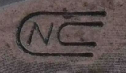
One of the more common brands you will see on bushings is Global CNC. Their bushings will frequently be stamped with this logo rather than saying "Global CNC" on them:
The inner diameter should be measured using calipers. Typically you can expect this to be a common fractional size such as 1/2", 5/8", 1 1/4", etc. If you are getting an unusual "off-size" measurement, check the size in millimeters as it may be a metric size.
Note: When entering a whole-number inch size, always include the " sign. The " sign should not be included for any size including a fraction or decimal. So, for example: If a bushing's I.D. is exactly one inch, it should be entered as 1" and not just 1. If the I.D. is one and a half inches, it should be entered as 1 1/2 or 1.5 and not 1 1/2" or 1.5".
Metric size measurements should be entered with a lowercase "mm" (ex.: 16mm, 40mm).
Some bushings may have a Morse Taper size for the inner diameter. Morse taper bushings will usually have a small slot toward the end of the bushing, as can be seen in the picture below. Also look out for labeling that includes a "#" such as #3, #5 etc. This often refers to a MT size. The chart below details Morse Taper sizes (you will be using the "large end" measurement):

Like the inside diameter, the outer diameter of the bushing's body should be measured with calipers, and is typically a common fractional size (but can also be metric).
Some bushings have a completely round O.D., while others have one or more flat sides. Always measure the O.D. from one round side to the opposite round side - not flat to flat.
This should be measured with calipers just like the body O.D., however unlike the previous measurements the head O.D. is frequently not a common fractional or metric size and should be entered exactly as measured without any rounding.
If a bushing does not have a head that extends beyond the body (such as the one pictured in the "I.D." section above), simply leave this cell blank.
The overall length is simply the total length from one end of the bushing to the other. This can be measured with calipers or even a tape measure as this measurement does not need to be as precise as the I.D. / O.D. measurements.
There are several different styles of bushings, the most common of which will be described below:
(Click to jump to section)
![]()
![]()
![]()
![]()
![]()
![]()
![]()

Sometimes thought of as "universal" bushings, "C" Bushings have slots for set screw clearance which allows them to be used interchangeably on any CNC turning machine regardless of brand. Set screws from the machine or tool holder are tightened through the slot and into a flat section on the held tool's shank.
Slot Width: Measure with calipers per the image below. This will not always be an "onsize" measurement and so should not be rounded if it is more than .005" away from a fractional size.


Another "universal" type, "CA" Bushings have their own set screws which are used for clamping rather than relying on the set screws of a tool holder or CNC machine. This means that tools can be pre-set before inserting the bushing into a holder.
Set Screw Hole Dia.: Remove one of the screws with an allen wrench and measure its outer diameter with calipers. This should typically be an "onsize" such as 1/4" or 5/16", and frequently may be a metric size. Be sure to insert the screw back into the bushing afterward.
Hole Distance (Center to Center): This does not apply to this style and can be left blank.

"Z" Bushings combine aspects of both the "C" and "CA" styles, having both a clearance slot as well as set screws in the head for additional security.
Slot Width: Measure with calipers per the image below. This will not always be an "onsize" measurement and so should not be rounded if it is more than .005" away from a fractional size.


"B" Bushings are designed to hold tools which do not have flats on their shanks. They are split down the sides and have a flat on the O.D. The bushing clamps around the tool as set screws are tightened into the flat part of the bushing, as shown in the diagram above.

"J" Bushings have two (or sometimes more) set screw clearance holes. Unlike bushings with slots, they can only be used on machines that match their hole pattern. Like slotted bushings, set screws are tightened through the holes into a flat section on the held tool's shank.
Set Screw Hole Dia.: Measure the inner diameter of one of the clearance holes with calipers. This will not always be an "onsize" measurement and so should not be rounded if it is more than .005" away from a fractional size.
Hole Distance (Center to Center):
First measure the distance from the outer edge of one hole to the opposite outer edge of the other. Next, measure the I.D. of one of the holes and subtract this number from the first number. This will give you the center-to-center distance between the holes.
Note that the hole distance may not be a common size, and frequently it will be a metric size even if the rest of the bushing's measurements are nominal.
If a bushing has only a single clearance hole (which is uncommon), leave this blank.


"BJ" Bushings combine the split design of Style "B" with the clearance holes of Style "J", allowing them to be used for both tools with and without flats on their shanks. Like Style "J", the clearance holes can only be used with machines or tool holders that match the bushing's hole pattern. You may also see this style with a clearance slot rather than holes.
Set Screw Hole Dia. & Hole Distance (Center to Center): Refer to the information in the Style "J" section above.


Style "LB" (left) and "LBF" (right) are very similar to styles "J" and "CA" respectively, but are differentiated by the clearance notches in the head which allow coolant hoses to be run through. You may occasionally see these bushings with only one clearance notch. You may also see other styles of "coolant thru" bushings such as ones with slots rather than holes.
Set Screw Hole Dia. & Hole Distance (Center to Center): (Style LB only) Refer to the information in the Style "J" section above.
List any part numbers or other important labeling. Bushings often have their dimensions (I.D. and O.D.) labeled; this does not need to be included in labeling since this information is already included in the listing.
The "Filler" section is used to add other relevant information to the title which is not covered by the other sections. Fillers can be a good way to increase a listing's visibility - we always want to include as much information as possible that we think a customer might be searching for in order to make sure that our listing is coming up in their search results.
There is not necessarily one right answer when it comes to fillers, and often it will be up to you to decide what should and should not be added as filler. Bushings generally do not require much filler, but some possible fillers include:
-Secondary labeling or branding / product names
-"USA" or "USA Made" for any US Manufacturers (you may need quickly research a brand if you are not sure since this will not always be specifically labeled)
- Some bushings are split down the sides, such as the first example in the "Picturing" section of this FAQ. These bushings should always have "Split Sleeve" added to the title.
Note: Keep in mind that titles have a maximum limit of 80 characters.
Additional Specifications & Special Condition
The Additional Specifications section should be used for any secondary labeling or additional measurements that do not fit in the other sections of the listing. There is no character limit here so any relevant information that is not already covered should be included (within reason - we don't want to overload the listing with unnecessary information, so ask your trainer if you are not sure whether or not to include something in this section).
The Special Condition section should be used for any special notes about the item's condition such as damage or modification. Try to be specific when describing the condition, and reference pictures that point out the damage / modification if applicable. General wear and tear does not need to be mentioned, but anything that will affect the tool's usage should be included here.
Once all information is entered, click here for the next steps.