General Rules for New Gage Pictures:
1. White background. Make sure it is clean and try to minimize any wrinkles in the tarp. You may find it helpful to put a second, partially folded tarp on top in order to reduce wrinkles (just make sure your pictures are fully within the folded tarp - we do not want to see the edges in the pictures)
2. Gently wipe down the gages with a dry rag to get rid of any fingerprints before picturing
3. Do not remove any wax from the gages. If the gages are unwaxed, clean the threads using rubbing alcohol and a wire brush. Make sure that any and all residue is fully removed from the threads. It is recommended to wipe down the threads using a paper towel rather than a cleaning rag, as the rags will often leave behind bits of string / fluff that will show up in the pictures
4. Try to eliminate shadows as much as possible. This may require you to take multiple pictures in different areas of your picture station in order to find the "sweet spot" with the best lighting.
4. No watermarks!
5. White-background pictures often require additional editing once they have been moved from the SD card onto your desktop:
a. Open GIMP

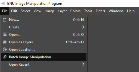
b. Select "File" -> "Batch Image Manipulation"
c. In the new window that appears, click "Add Images" and then "Add folders..."
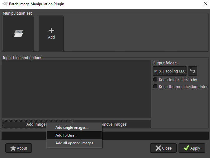
d. Navigate to the "Listing Picture" folder (or whichever folder your pictures are currently in), select the folder, and then click "Add" in the bottom right corner of this window, which will return you to the previous "Batch Manipulation" window

e. At the top of the window under "Manipulation Set", click "Add" and then "Color Correction"

f. Set the Brightness to 0.15 and check the box for "Automatic color levels correction", then click "OK"

g. On the right-hand side of the window you will see "Output folder:". Click on "M & J Tooling LLC" below this and select whichever folder you want the edited pictures to be saved to, such as an "Edited Pictures" folder on your desktop. Do not use the same folder that the unedited pictures are currently in, as this will overwrite them. We want to make sure we still have the original pictures in case anything goes wrong.

h. Finally, click "Apply" in the bottom right corner of the window. The editing process can take a few minutes, so move on to another task while you wait (such as beginning to fill out your listing template).
i. Once the editing is complete, review the edited pictures. If most of the pictures are too dark, washed out, or have a strong color tint, you will want to tweak the parameters set in step F and try again. Contact your trainer for help with changing these values to find the best settings.
j. If only a few pictures need adjusted, this can be done manually using the Windows Photo app. Double-click on a picture to open it, then click the "Edit Photo" icon (the one on the far left, shown below) followed by the "Adjustment" tab. Make changes as necessary (ask your trainer if you need help), and then save your changes using the blue "Save Options" button in the top-right corner.
![]()

k. Once all of the pictures have been edited appropriately, delete the original copies from your "Listing Pictures" folder, move the edited pictures into "Listing Pictures", and proceed with the batch image program as usual. DO NOT WATERMARK THESE PICTURES!
M & J Tooling Private Label Gages (SKU Code: MJ or LZ)
***Do Not Include Any Cases / Packaging In Pictures***
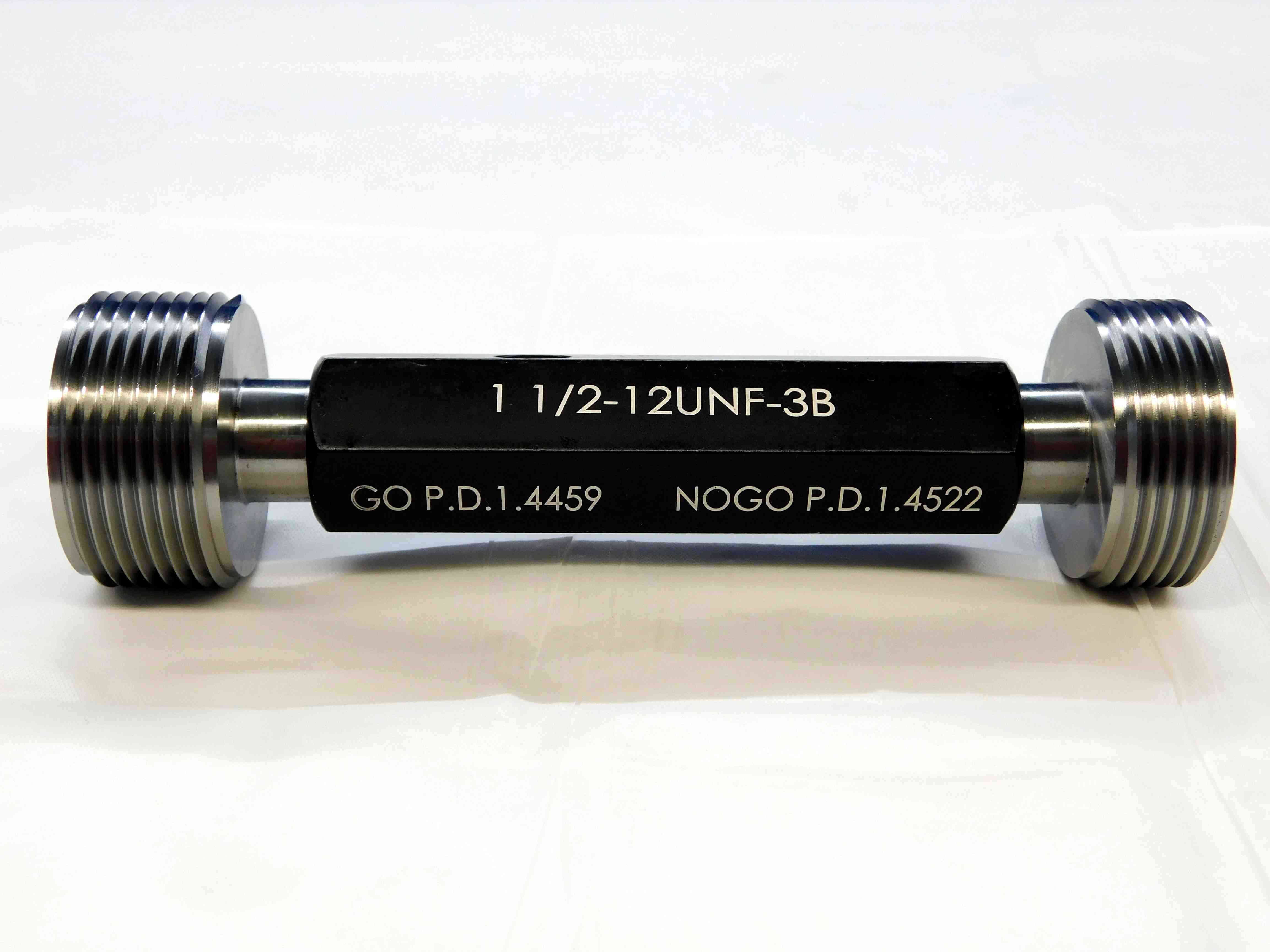
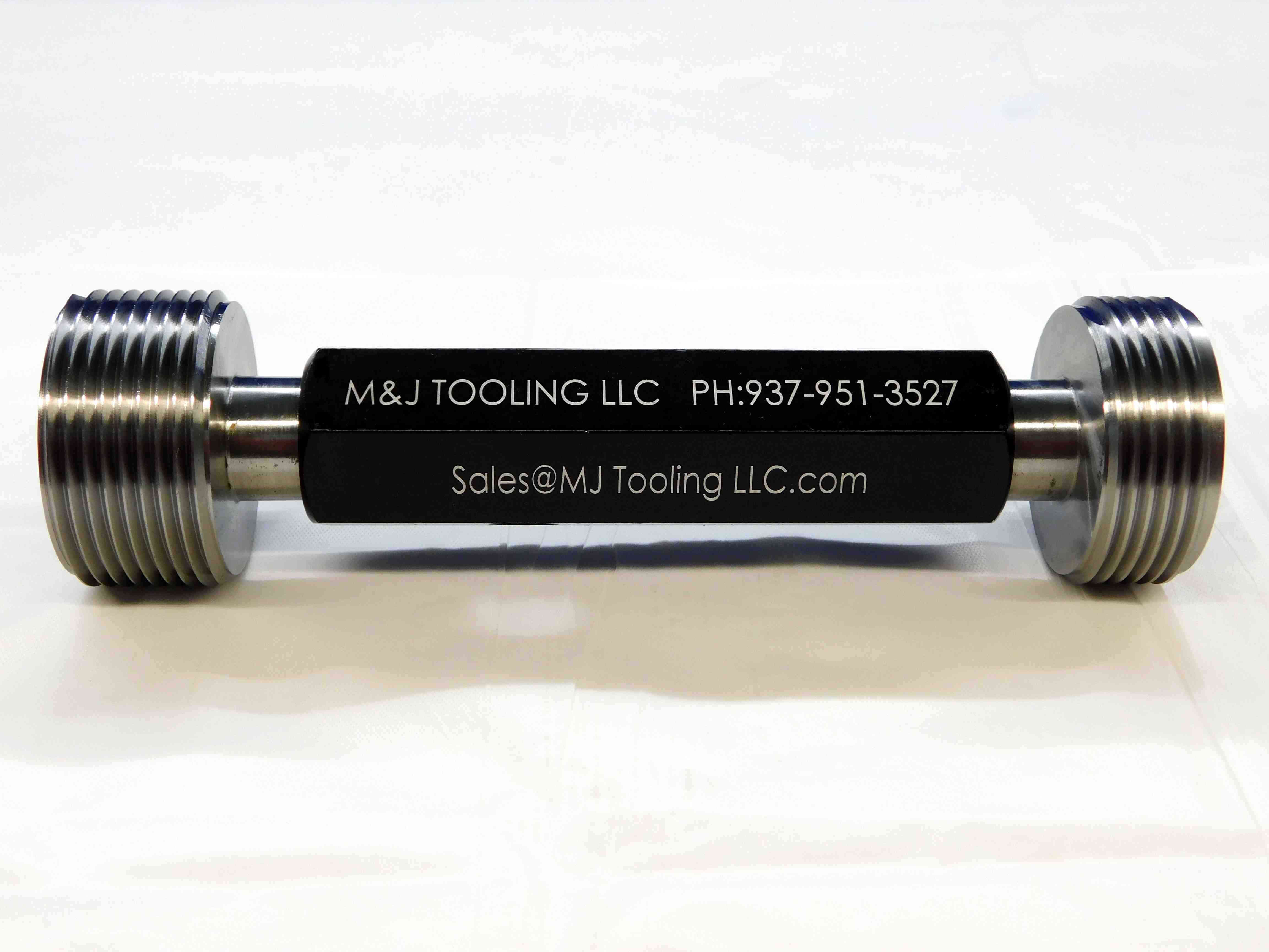
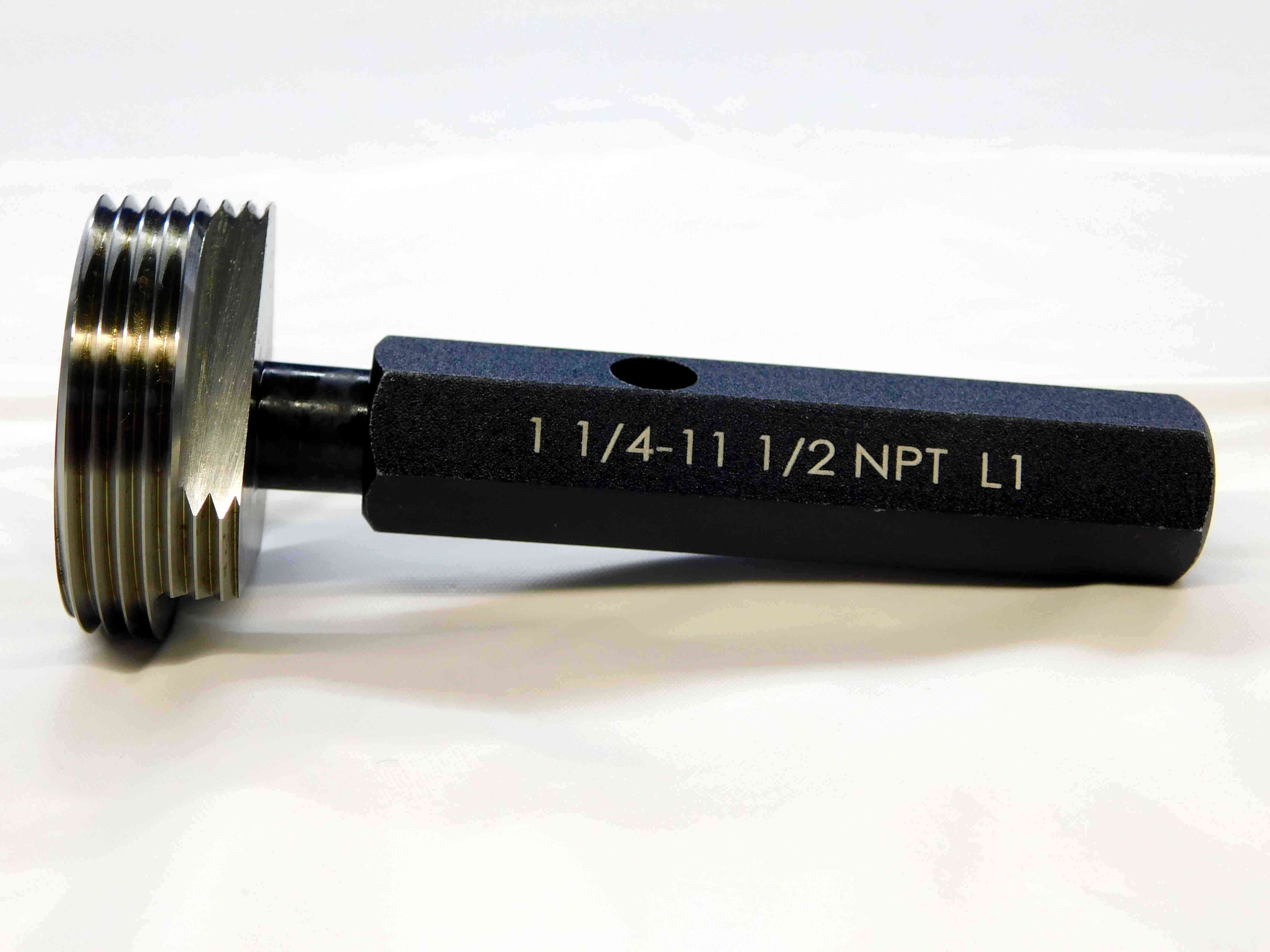
First picture: Place the gage in the center of the frame, with the "Go" member on the left and the "No Go" member on the right. Position the gage so that the size and pitch diameters are easily readable.
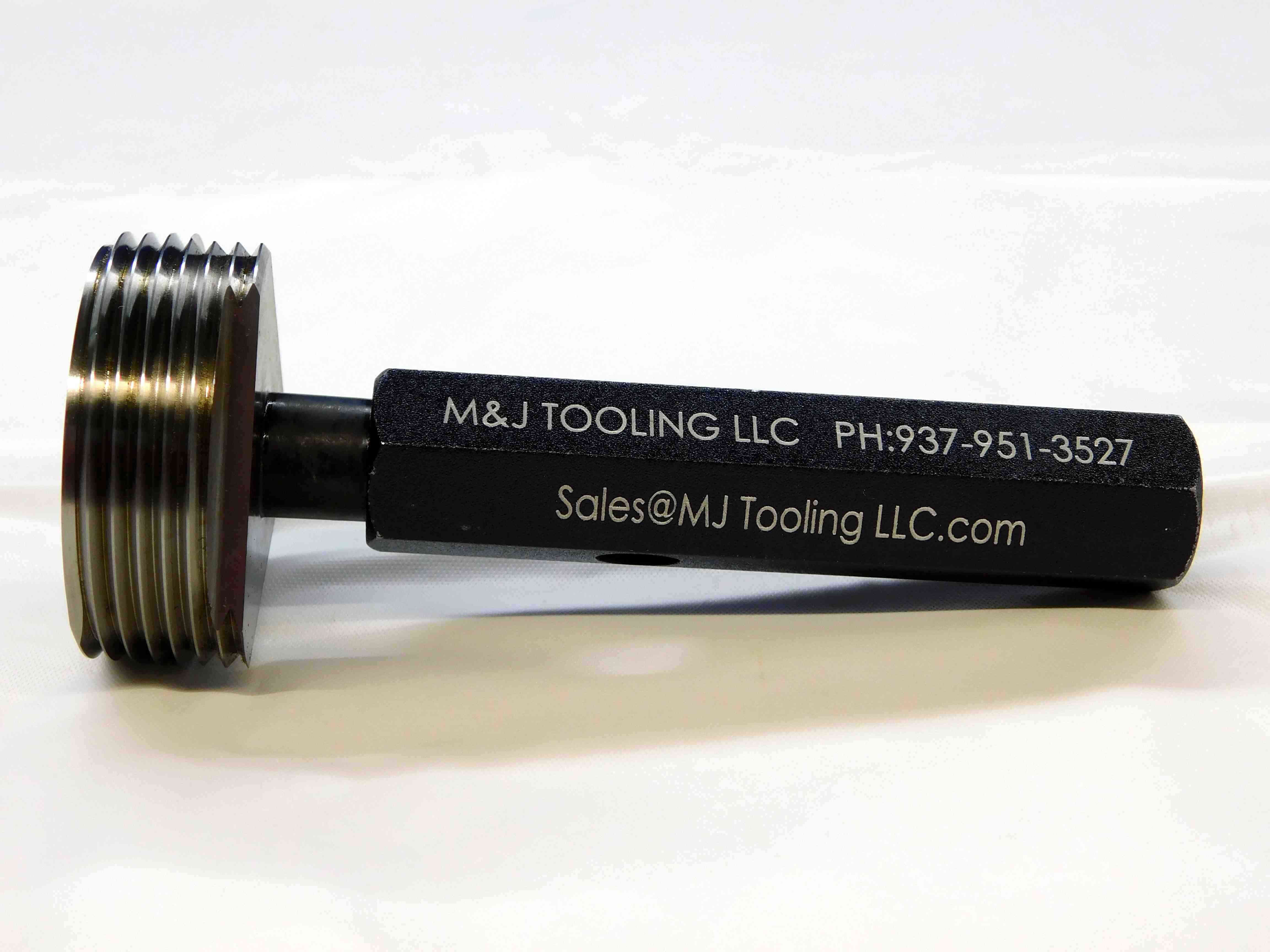
Second picture: Same as the first picture, but with the gage rotated so that the M & J Tooling company information on the back of the handle is visible.
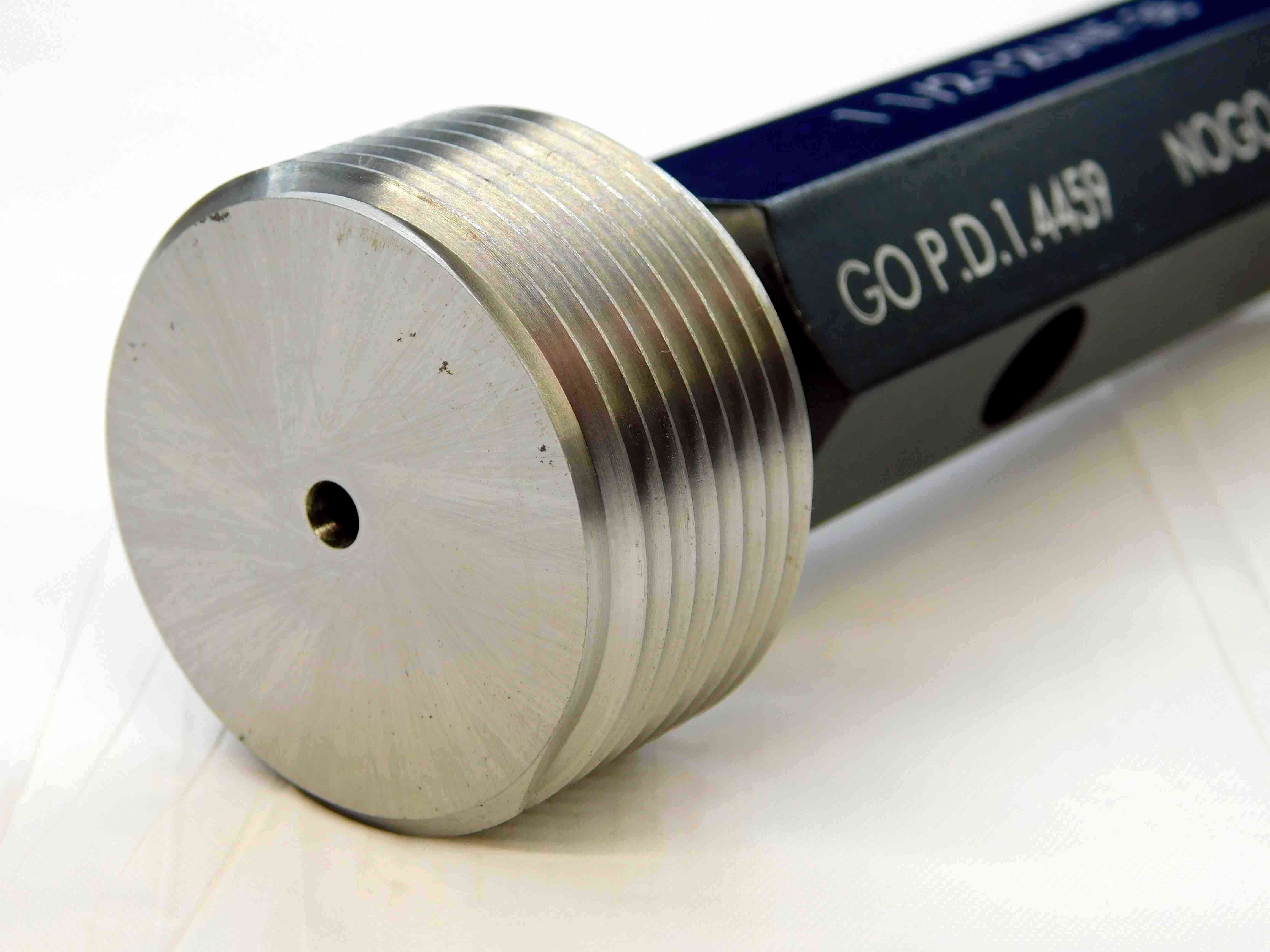
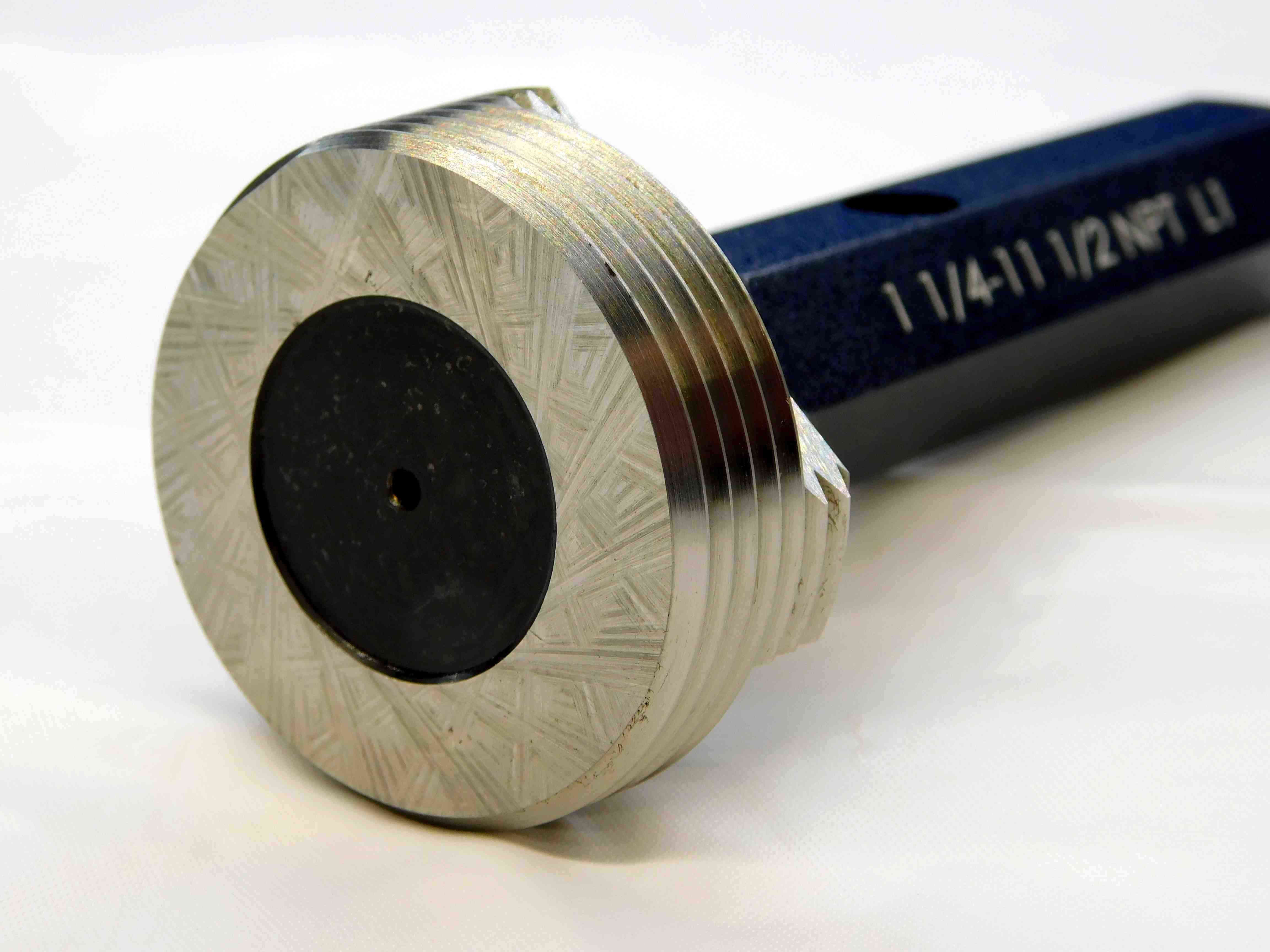
Third picture: A close-up of the "Go" member, taken at a three-quarters angle. Try to make sure the P.D. labeling is visible.
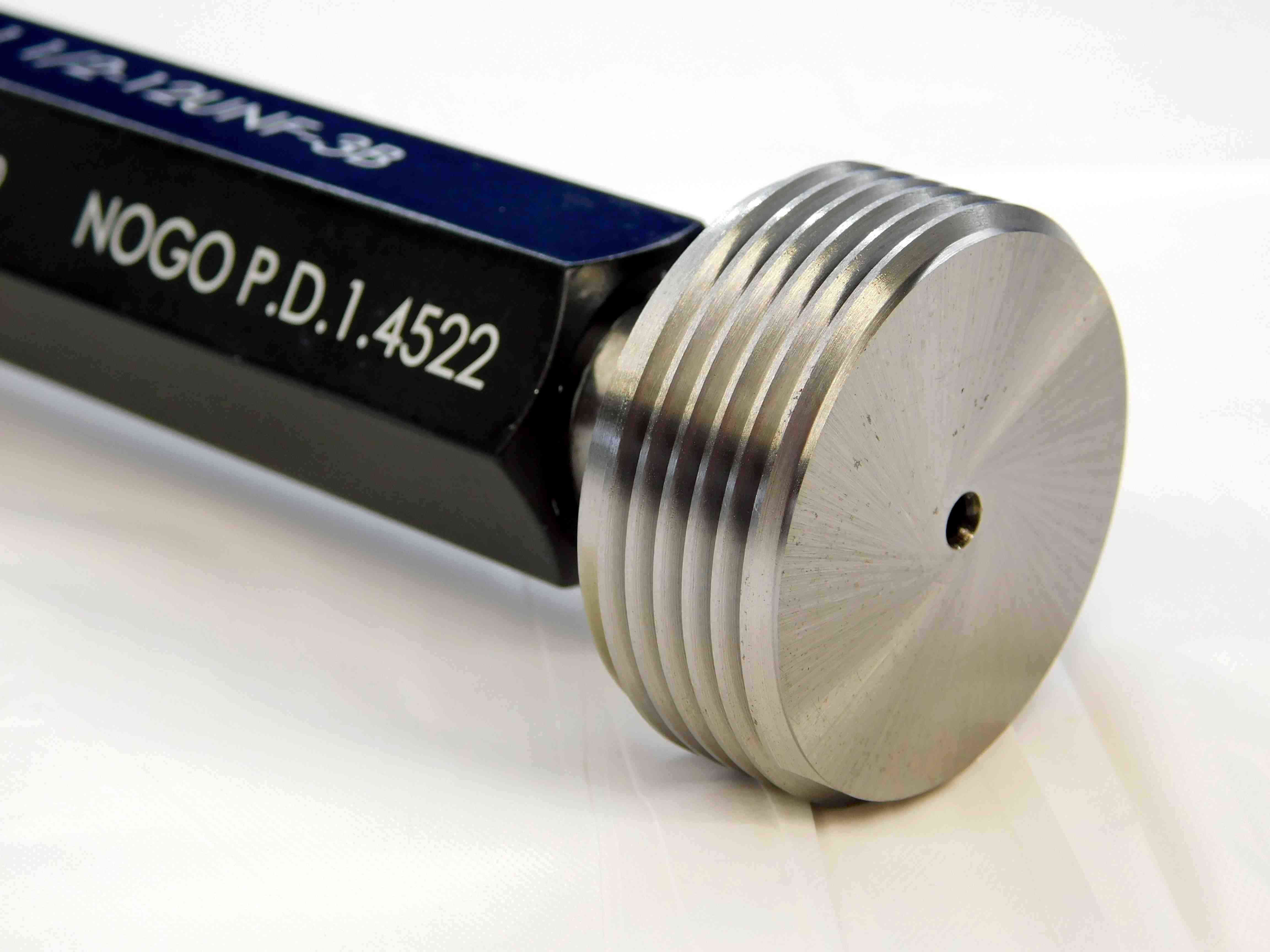
Fourth picture: A close-up of the "No Go" member, taken at a three-quarters angle. Try to make sure the P.D. labeling is visible. (If it is a single member pipe gage, skip this picture)
Refer to the examples below:
Example 1 (Go & No Go):
Example 2 (Single-Member):
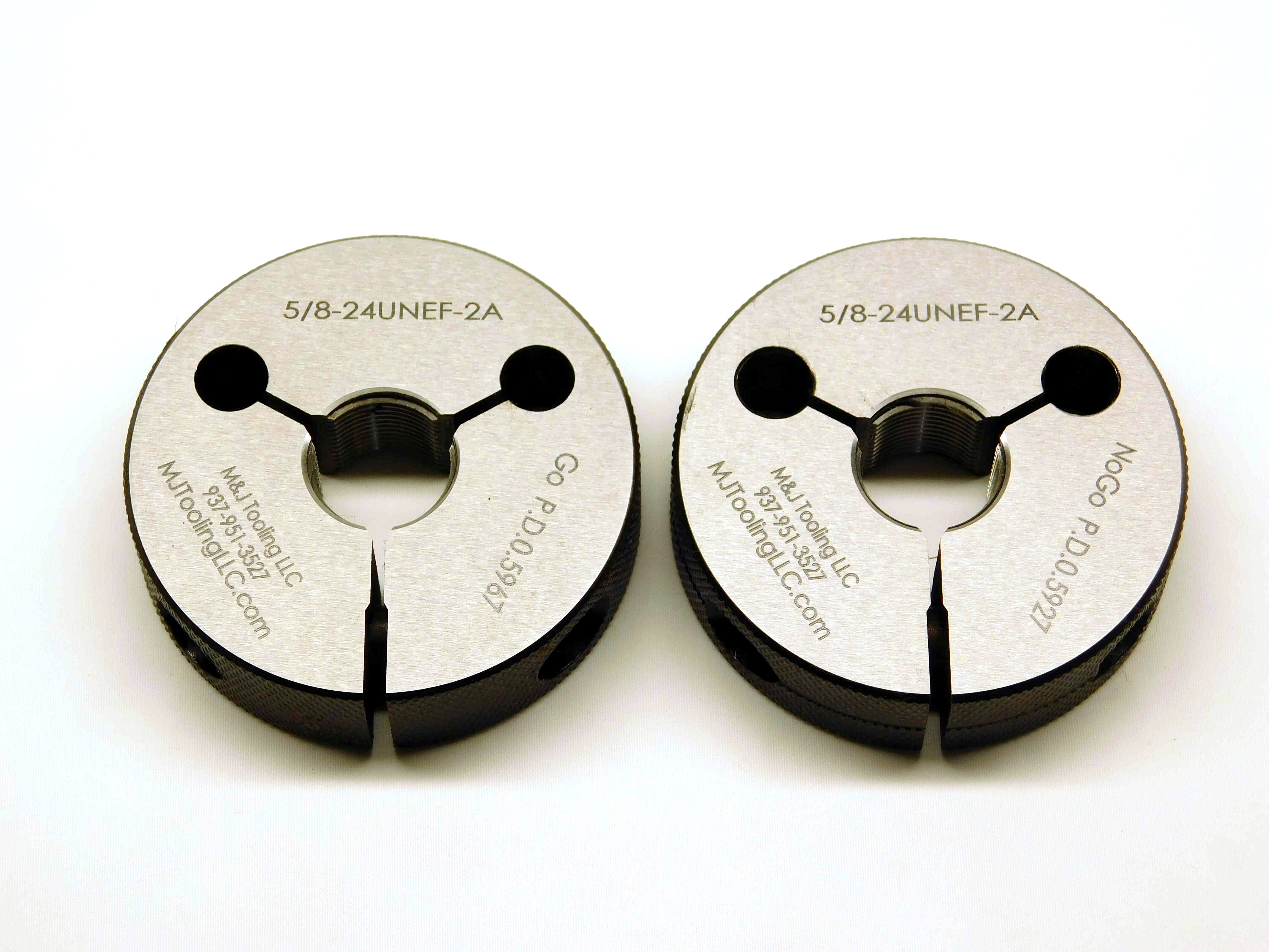
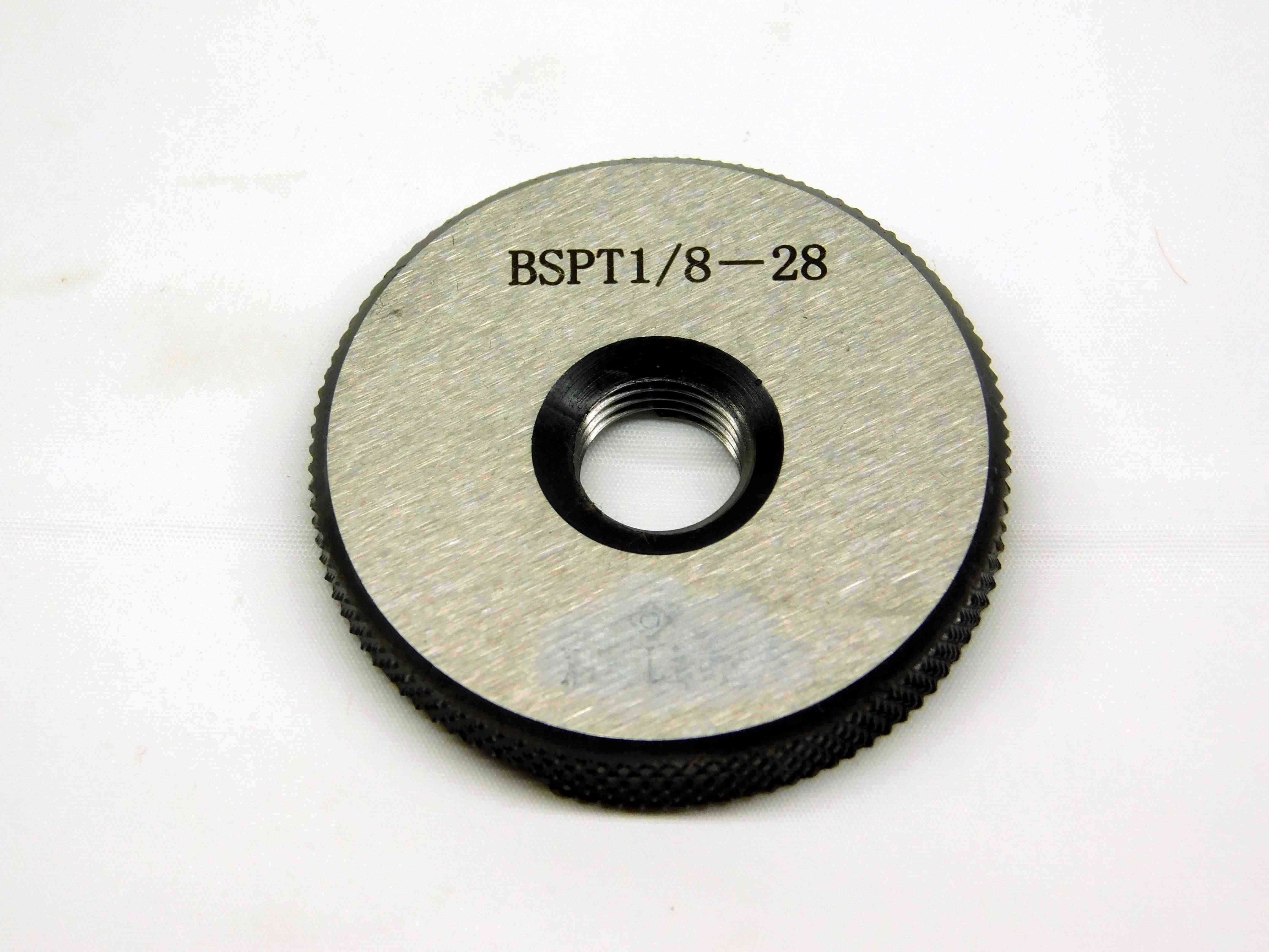
First picture: Place the gages in the center of the frame, with the "Go" ring on the left and the "No Go" ring on the right. If you are picturing just a single ring (such as a pipe gage), place the ring in the direct center of the frame. Orient the gages so that the size labeling is centered at either the top or bottom of the rings (whichever will be right-side-up).
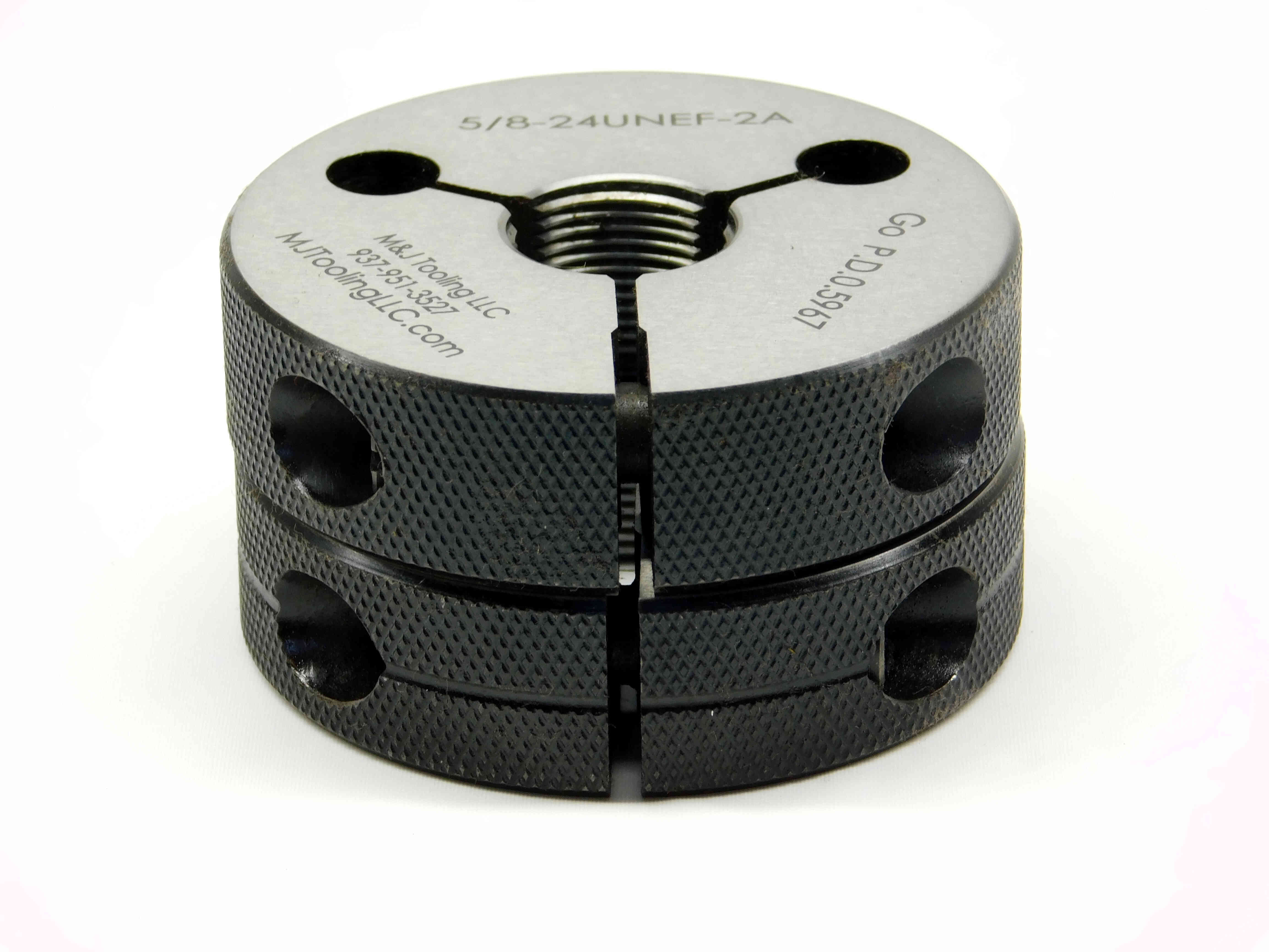
Second picture: A picture of the side of the rings, showing the adjustment screws. If the rings are solid (non-adjustable), skip this picture.
Third picture: A close-up of the M & J Tooling company information printed on the ring (if present - otherwise, skip this picture).
Refer to the examples below:
Example 1 (Adjustable):

Example 2 (Solid):
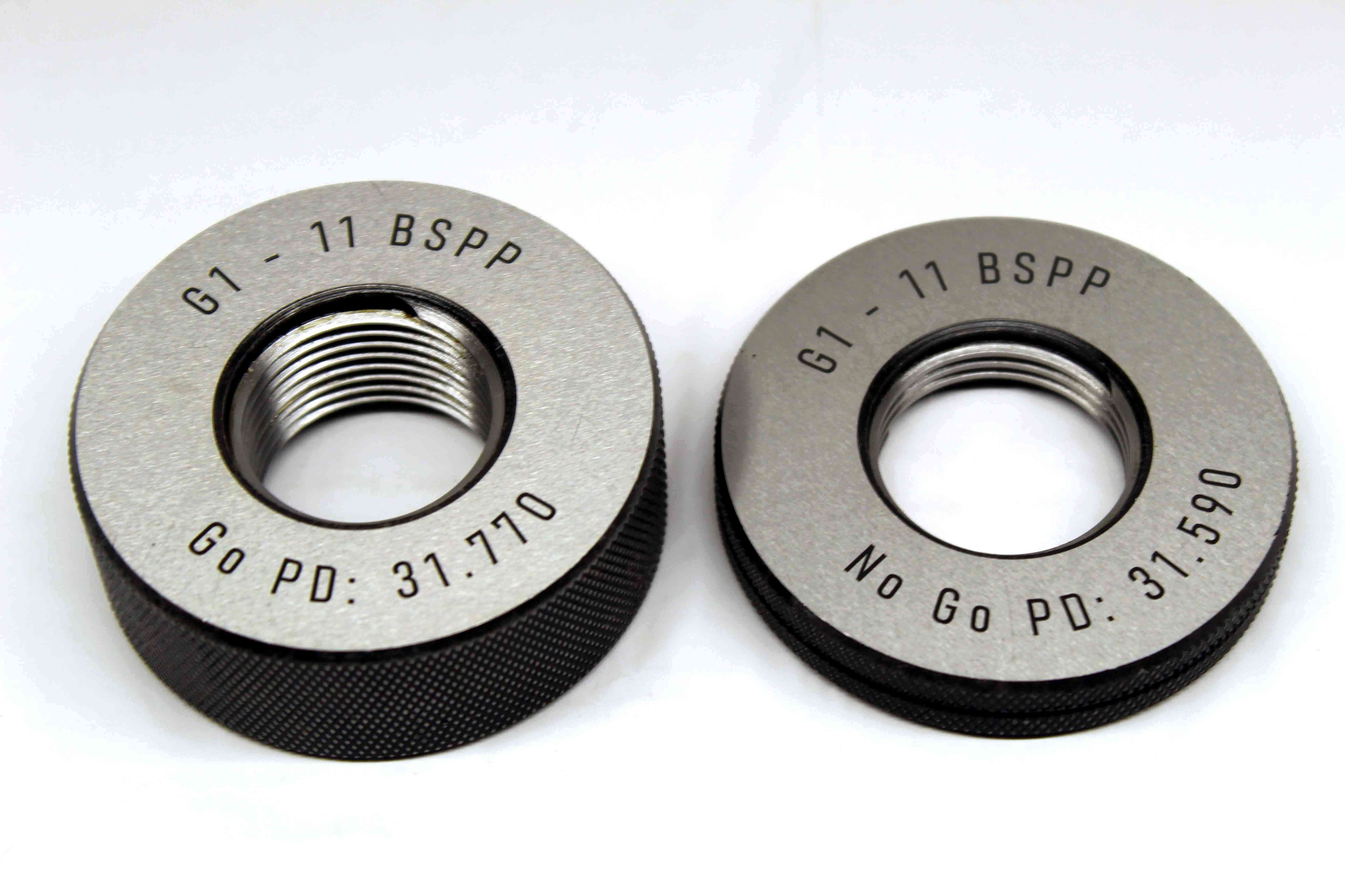
Example 3 (Single Ring):
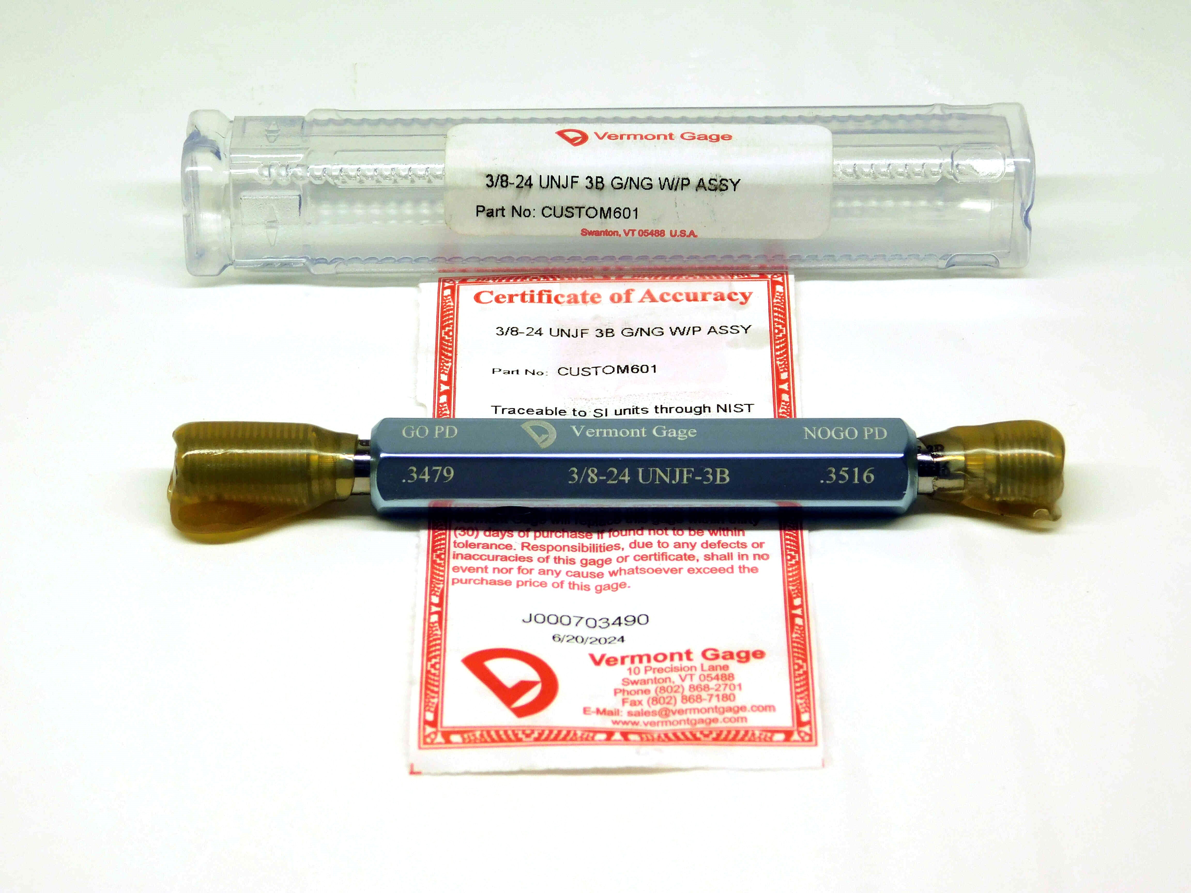
First picture: Place the gage in the center of the frame, with the "Go" member on the left and the "No Go" member on the right. Position the gage so that the size and pitch diameters are easily readable. Vermont gages should always come with a "Certificate of Accuracy". This should be unrolled and flattened out and placed underneath the gage. If there is a case, it should be placed behind the gage.
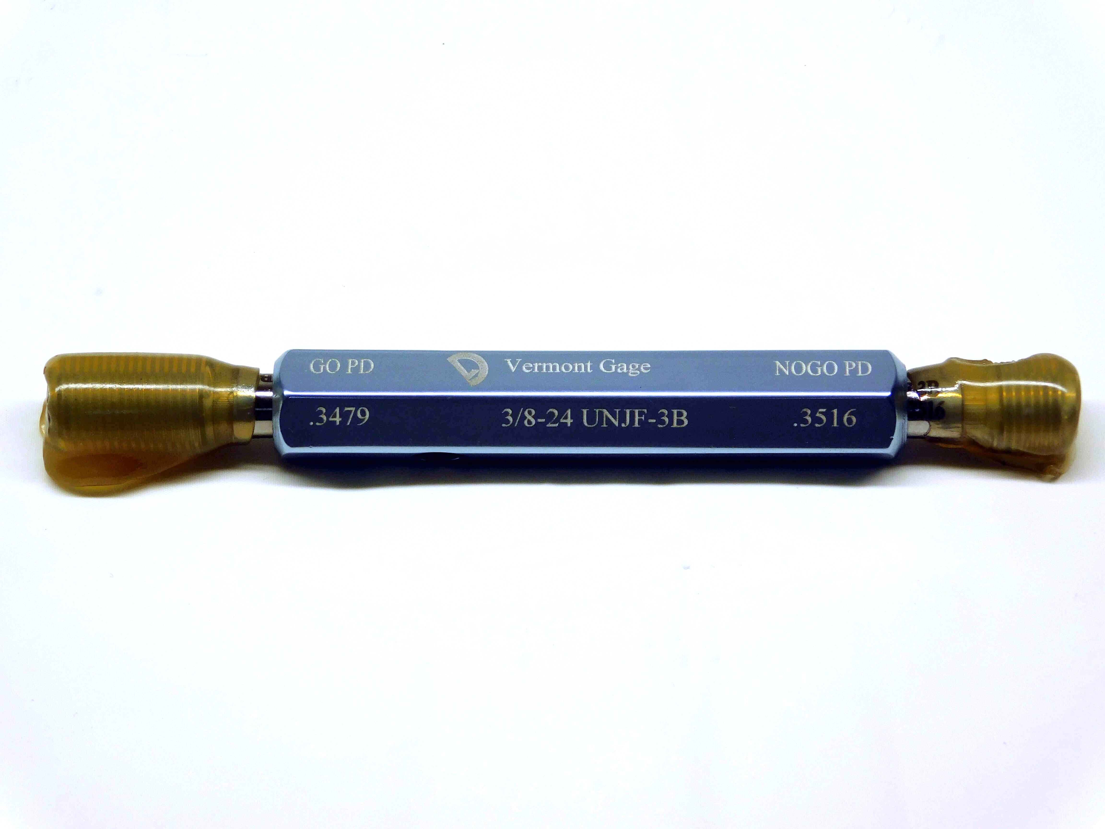
Second picture: Remove the case and cert and take a picture of just the gage, centered in the frame with labeling showing like in the first picture.
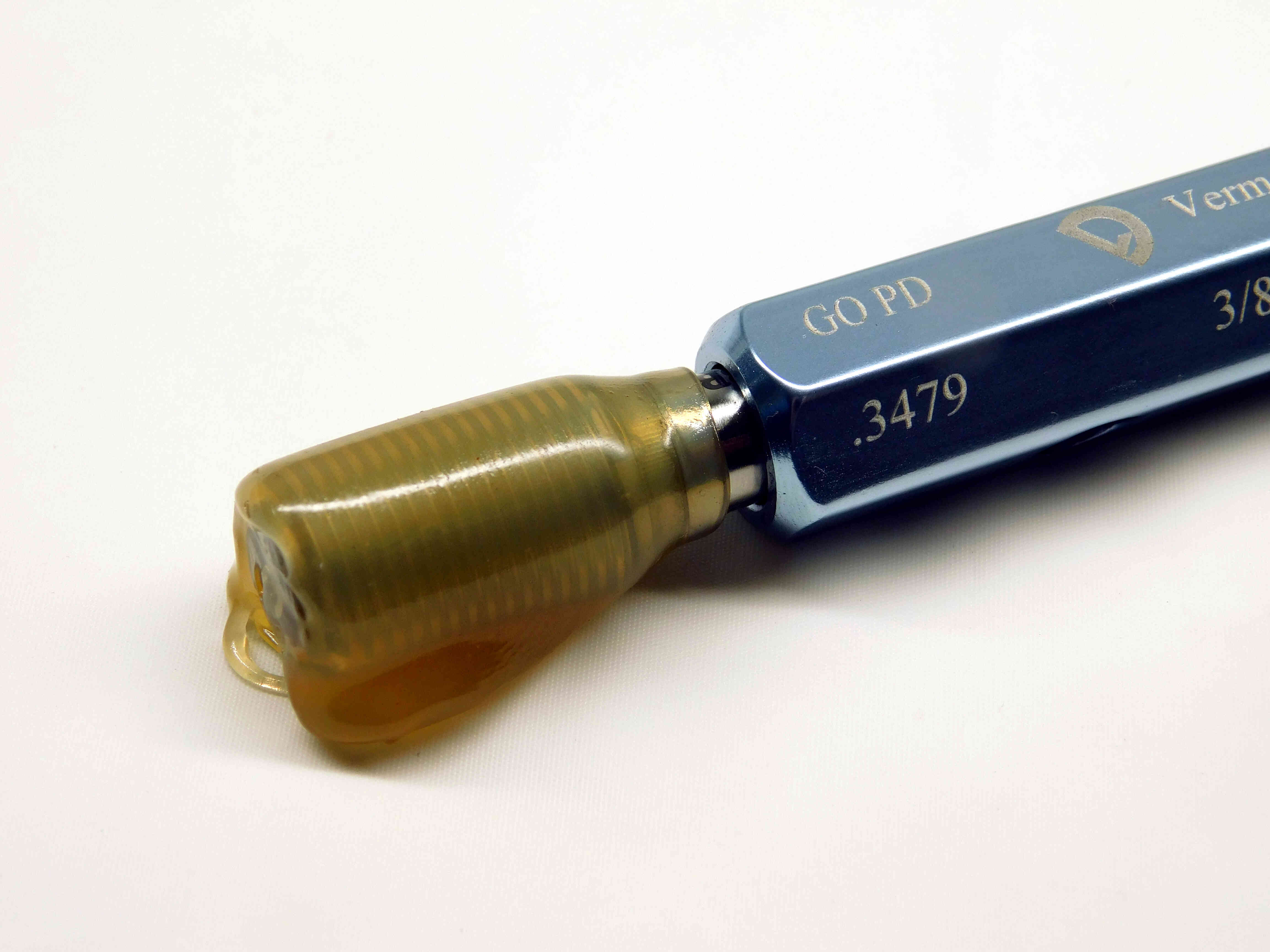
Third picture: A close-up of the "Go" member. Try to make sure the P.D. labeling is visible. Try to align the wax so that you can see through to the threads.
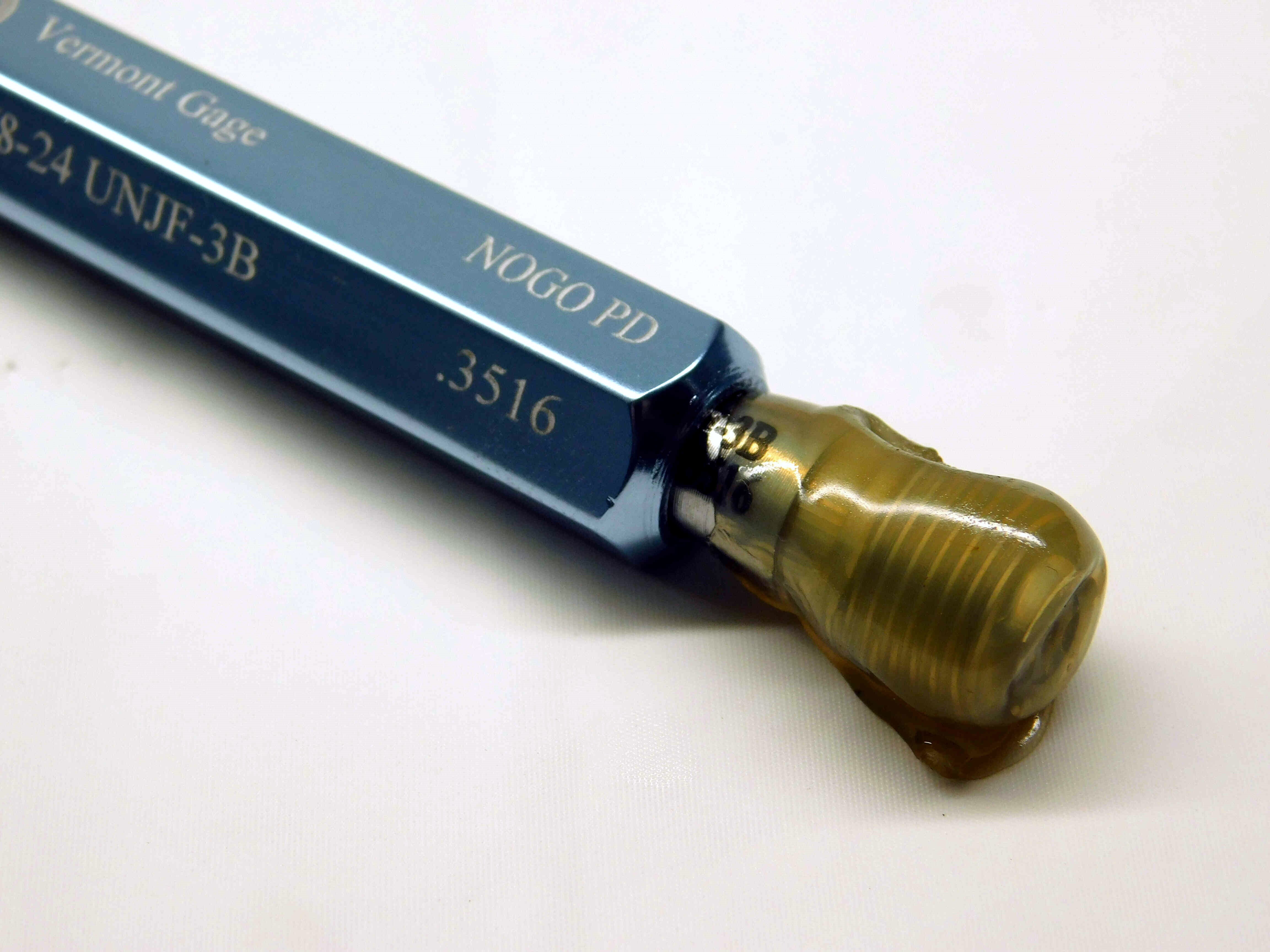
Fourth picture: A close-up of the "No Go" member. Try to make sure the P.D. labeling is visible. Try to align the wax so that you can see through to the threads. (If it is a single member pipe gage, skip this picture)
Refer to the example below:
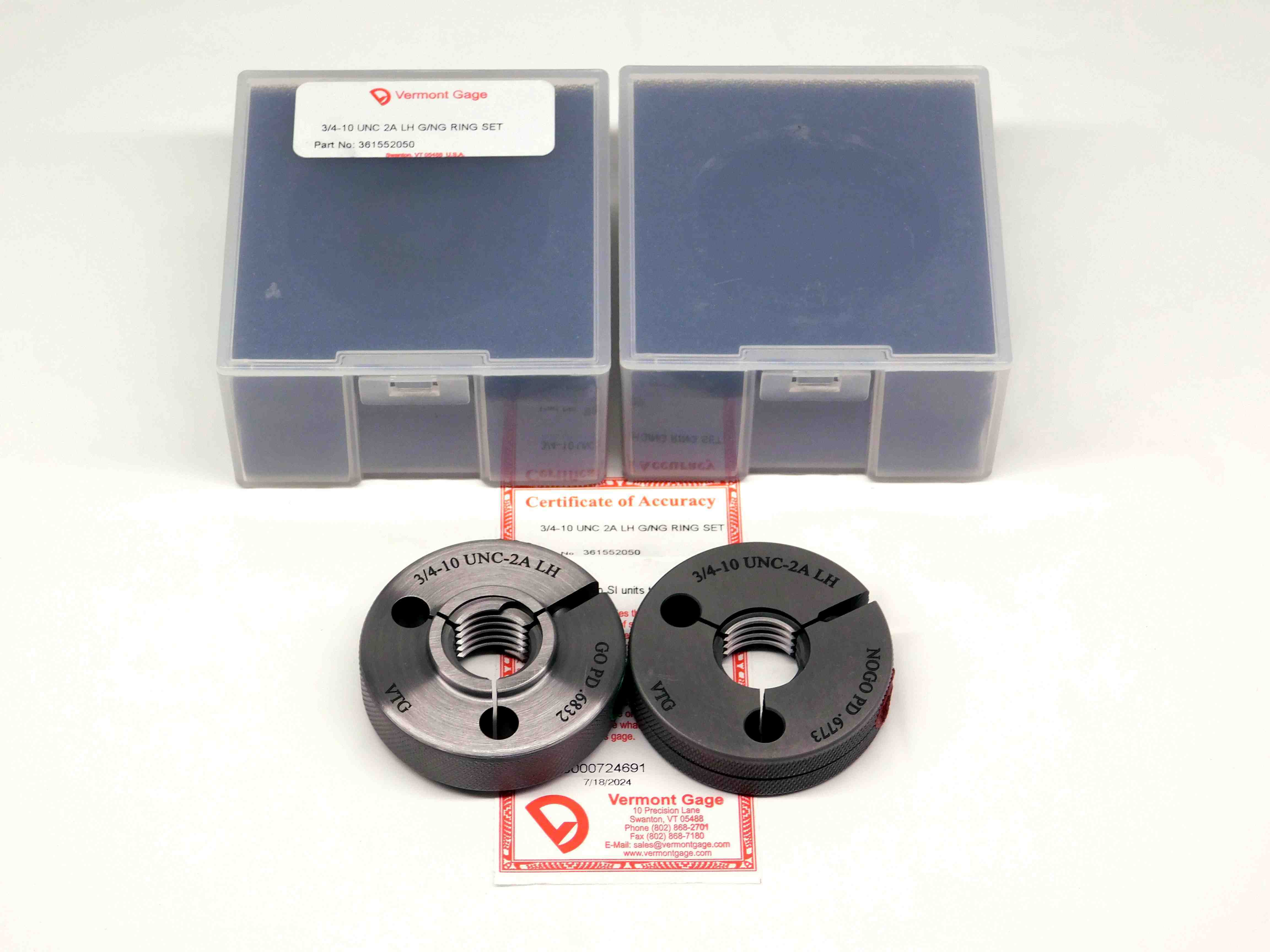
First Picture: Place the rings in the lower-center of the frame (due to the space that will taken up by the cases), with the "Go" ring on the left and the "No Go" ring on the right. Orient the gages so that the size labeling is centered at either the top or bottom of the rings (whichever will be right-side-up). Vermont gages should always come with a "Certificate of Accuracy". This should be unfolded and flattened out and placed underneath the gages. Cases should be placed behind the gages, with any labeling visible and right-side-up.
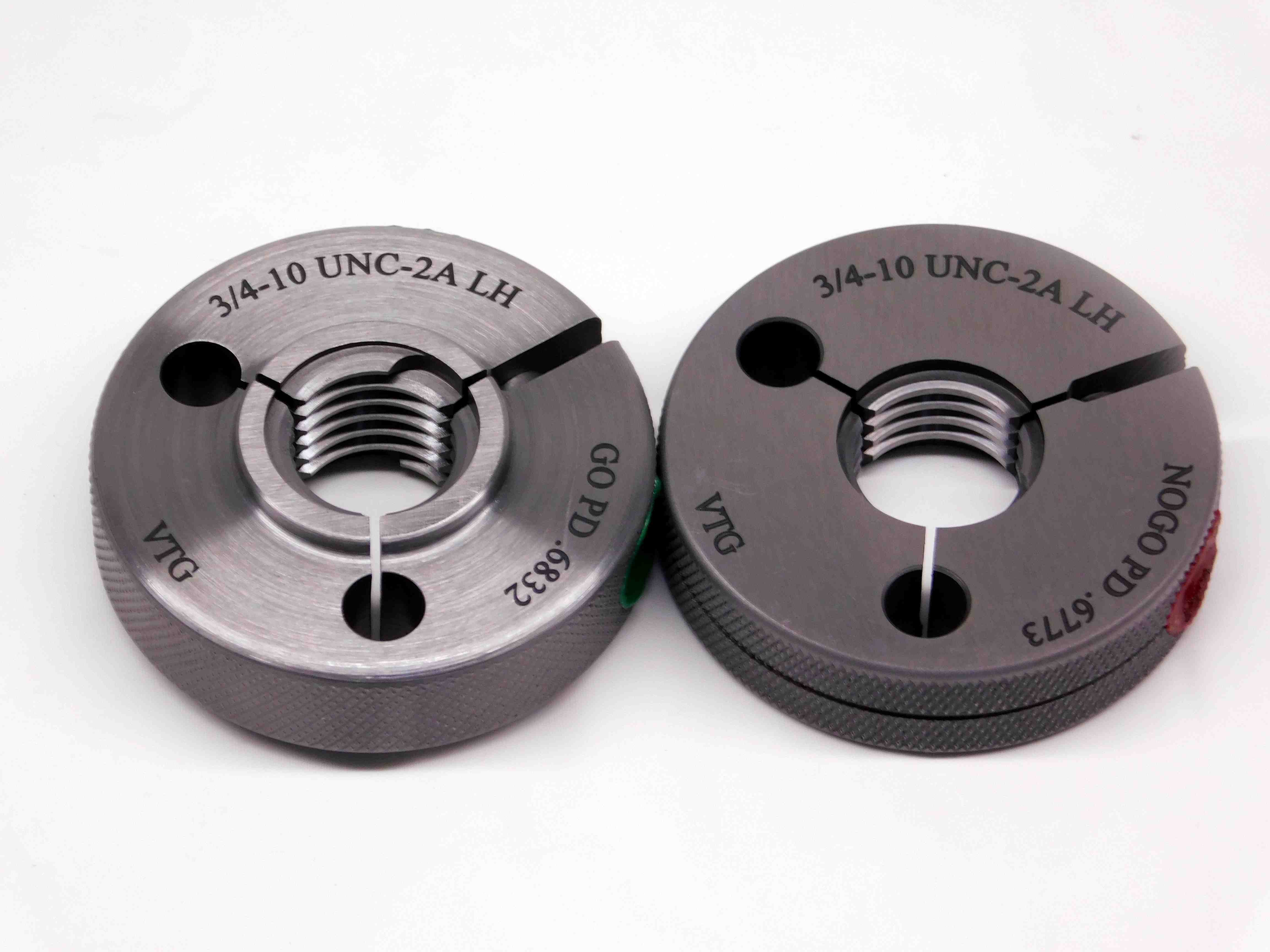
Second Picture: Remove the cases and cert and take a picture of just the ring gages, centered in the frame with labeling showing like in the first picture.
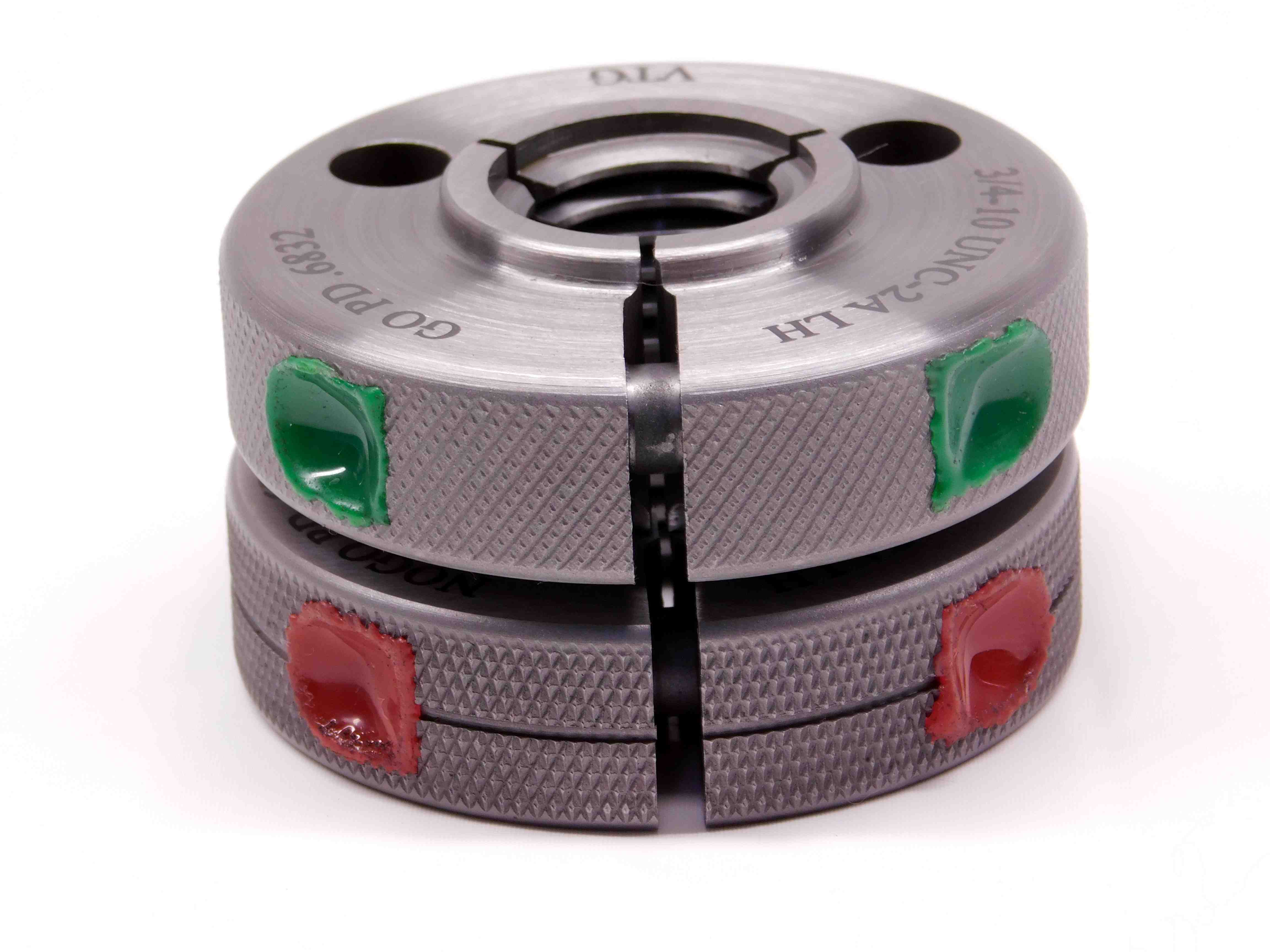
Third Picture: A picture of the side of the rings, showing the edge wax and adjustment screws.
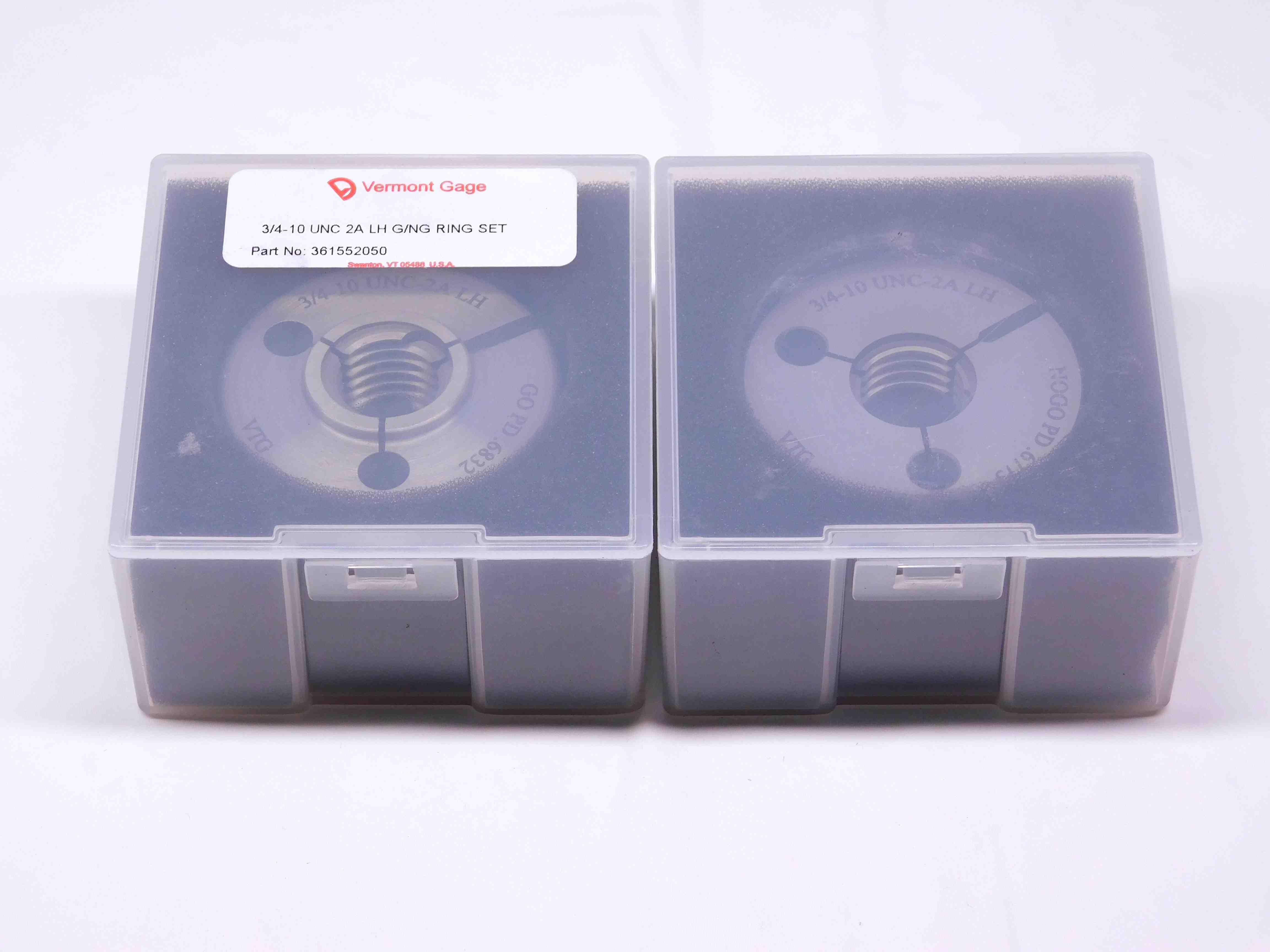
Fourth Picture: A picture of the gages inside of their (closed) cases. Any labeling on the cases should be visible and right-side-up.
Refer to the example below:
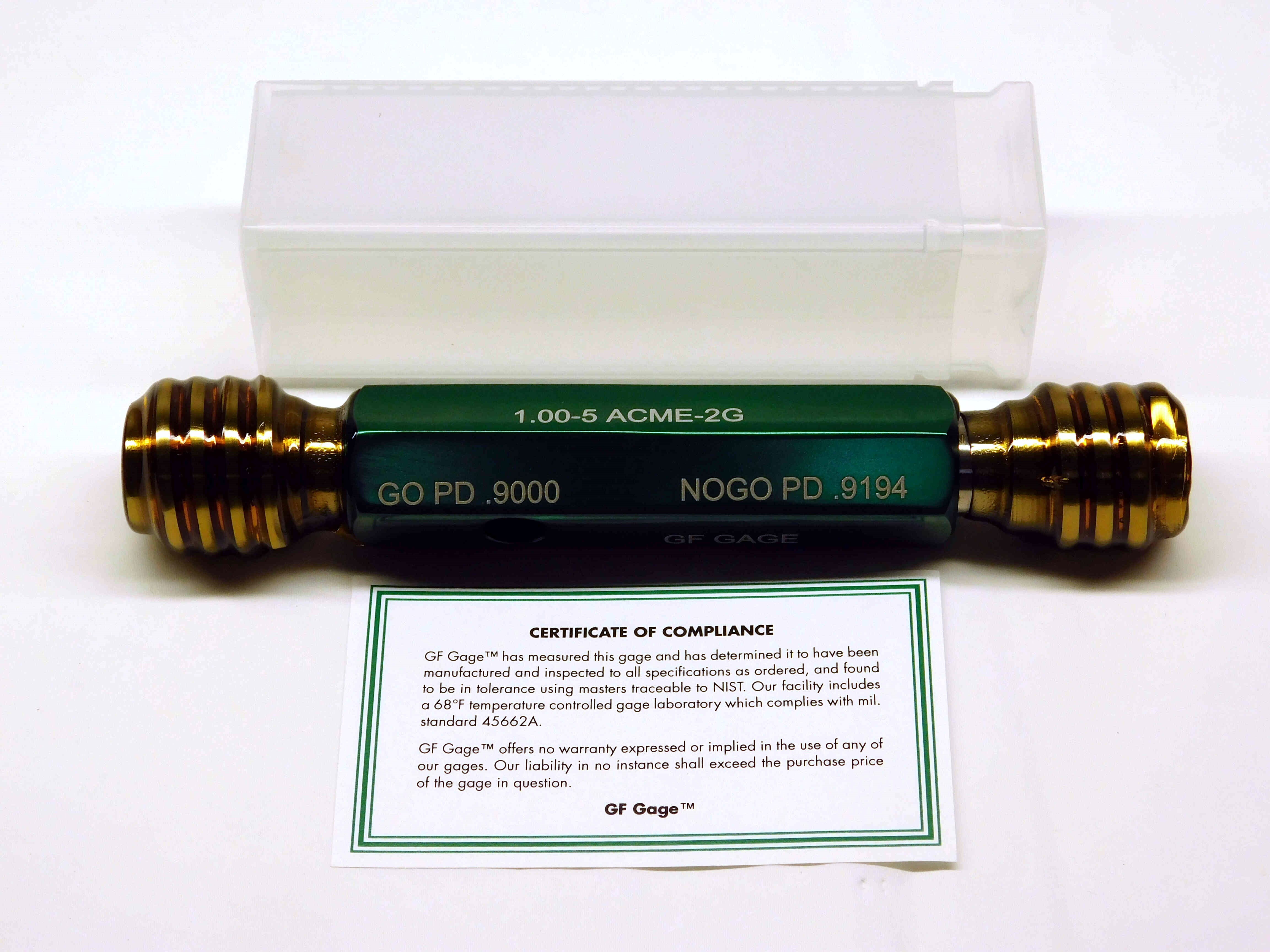
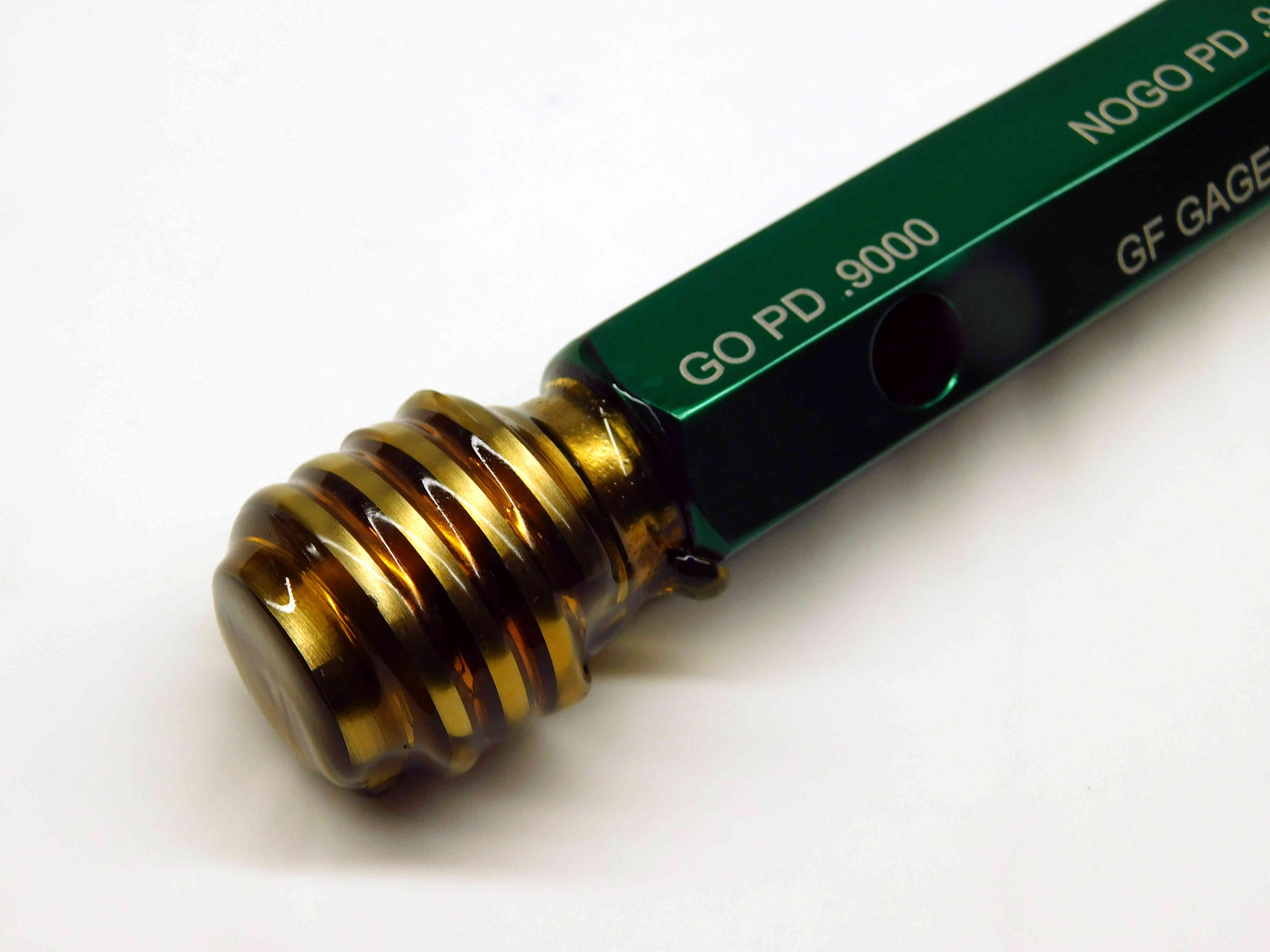
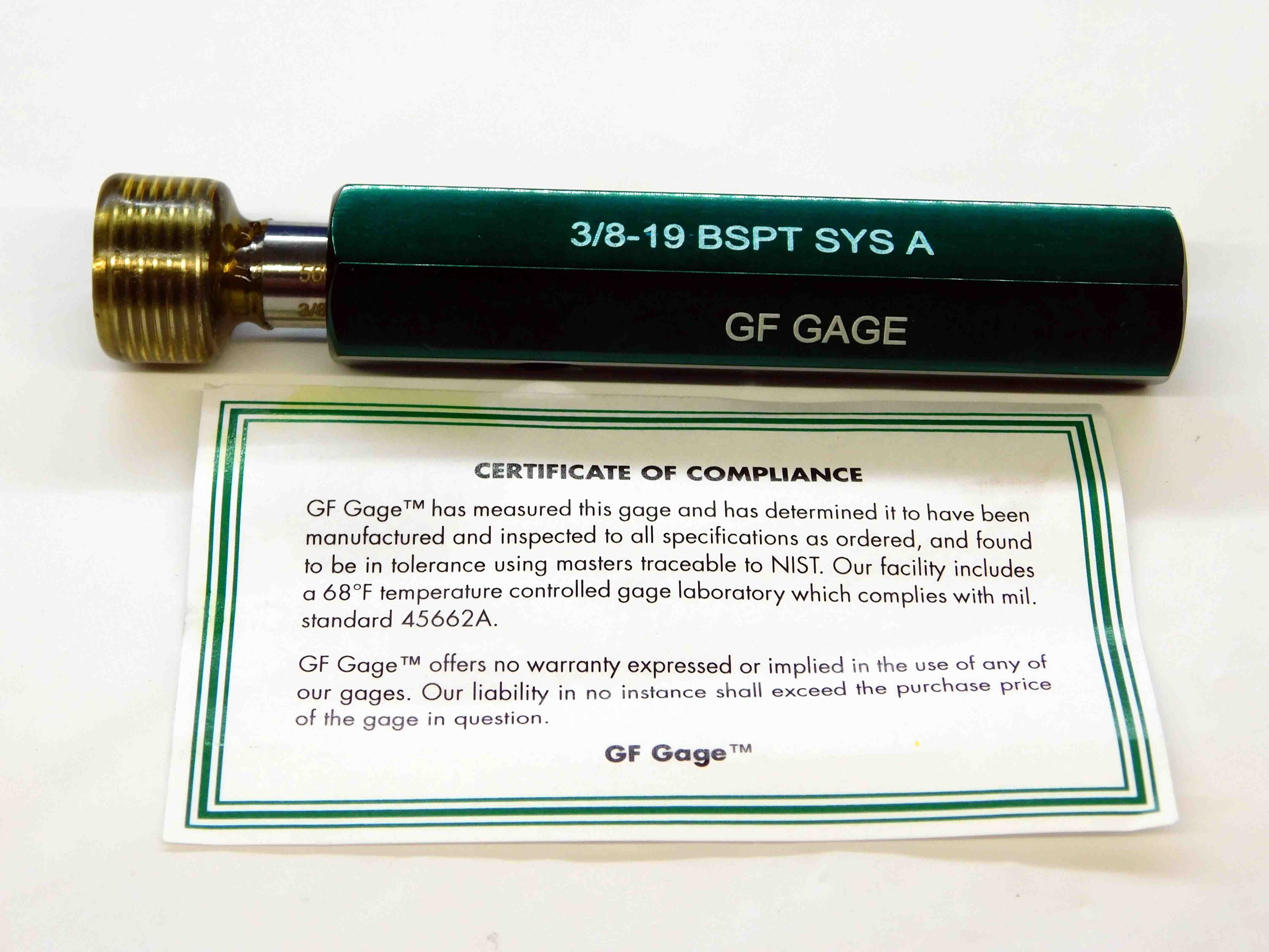
First picture: Place the gage in the center of the frame, with the "Go" member on the left and the "No Go" member on the right. Position the gage so that the size and pitch diameters are easily readable. GF gages should always come with a "Certificate of Compliance". This should be placed in front of the gage. If there is a case, it should be placed behind the gage.
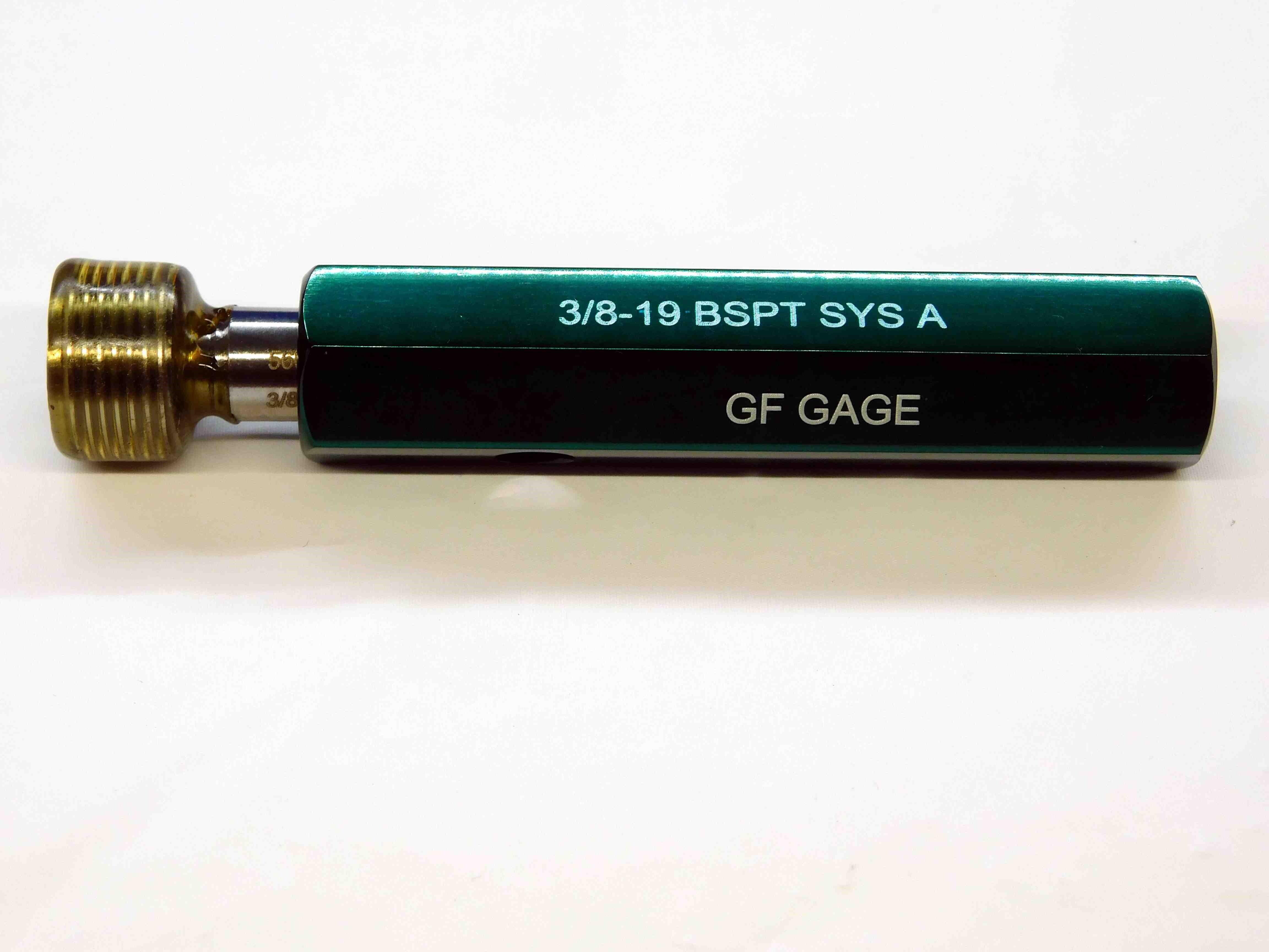
Second picture: Remove the case and cert and take a picture of just the gage, centered in the frame with labeling showing like in the first picture.
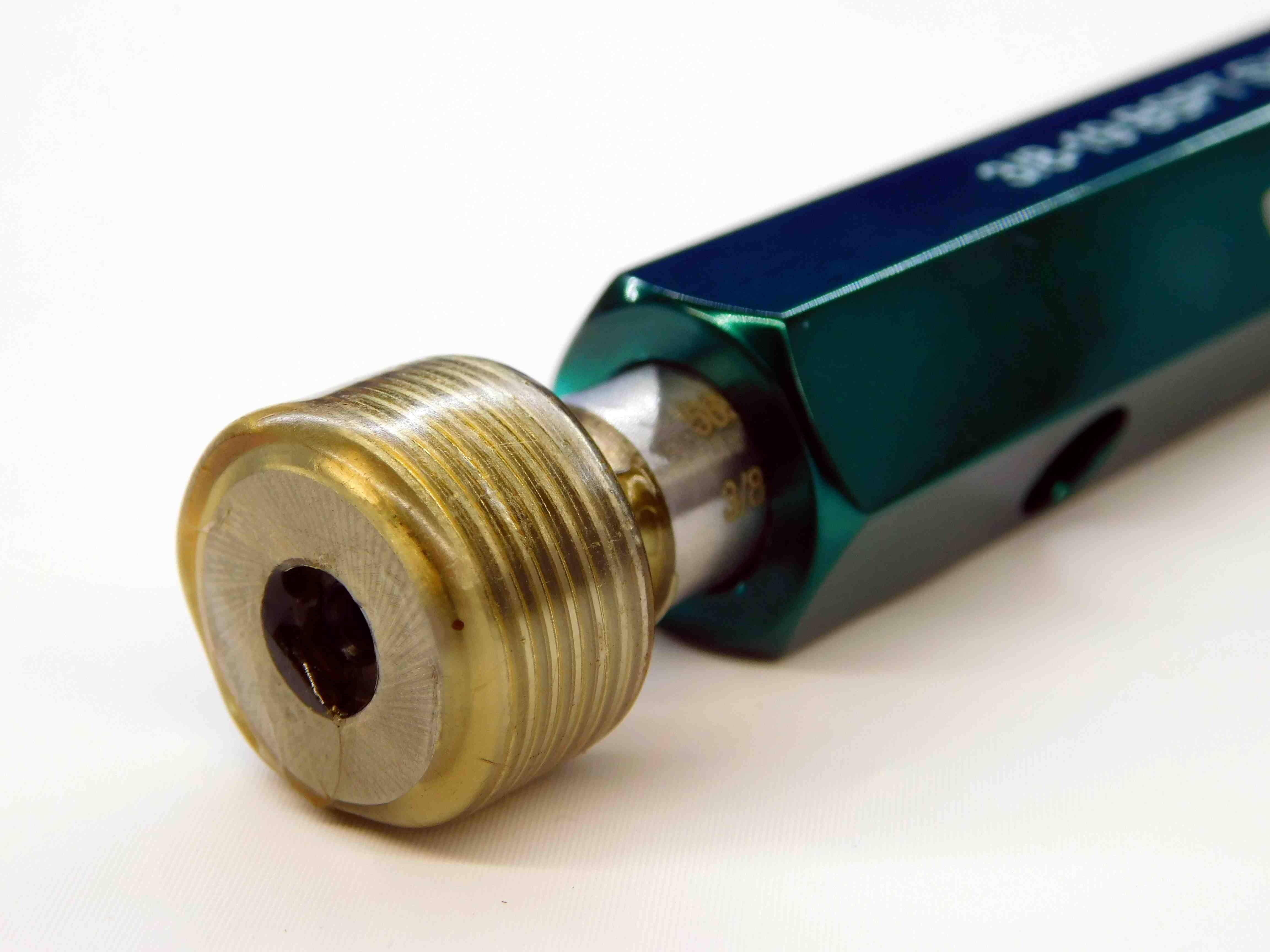
Third picture: A close-up of the "Go" member. Try to make sure the P.D. labeling is visible. Try to align the wax so that you can see through to the threads.
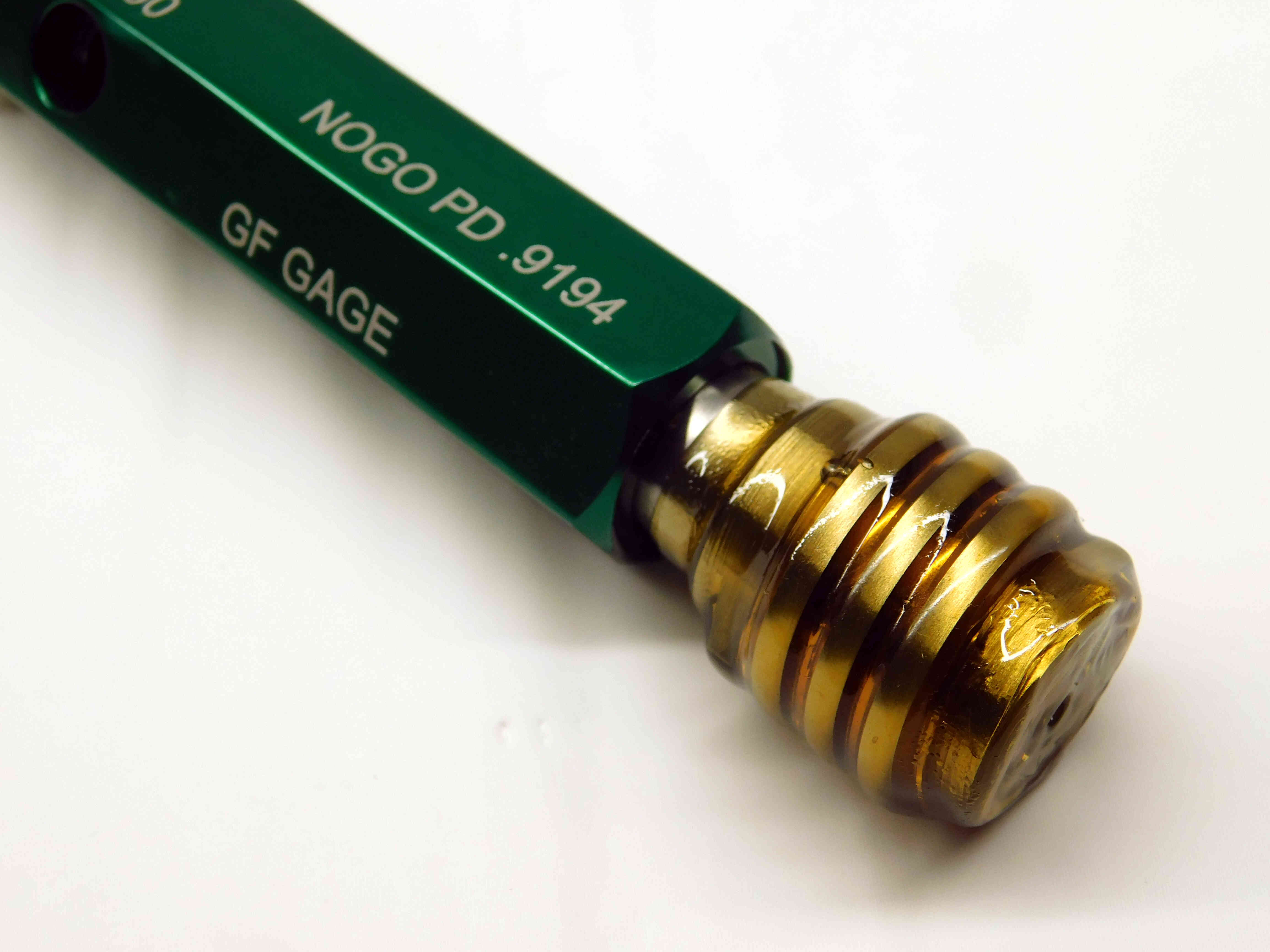
Fourth picture: A close-up of the "No Go" member. Try to make sure the P.D. labeling is visible. Try to align the wax so that you can see through to the threads. (If it is a single member pipe gage, skip this picture)
Refer to the examples below:
Example 1 (Go & No Go):
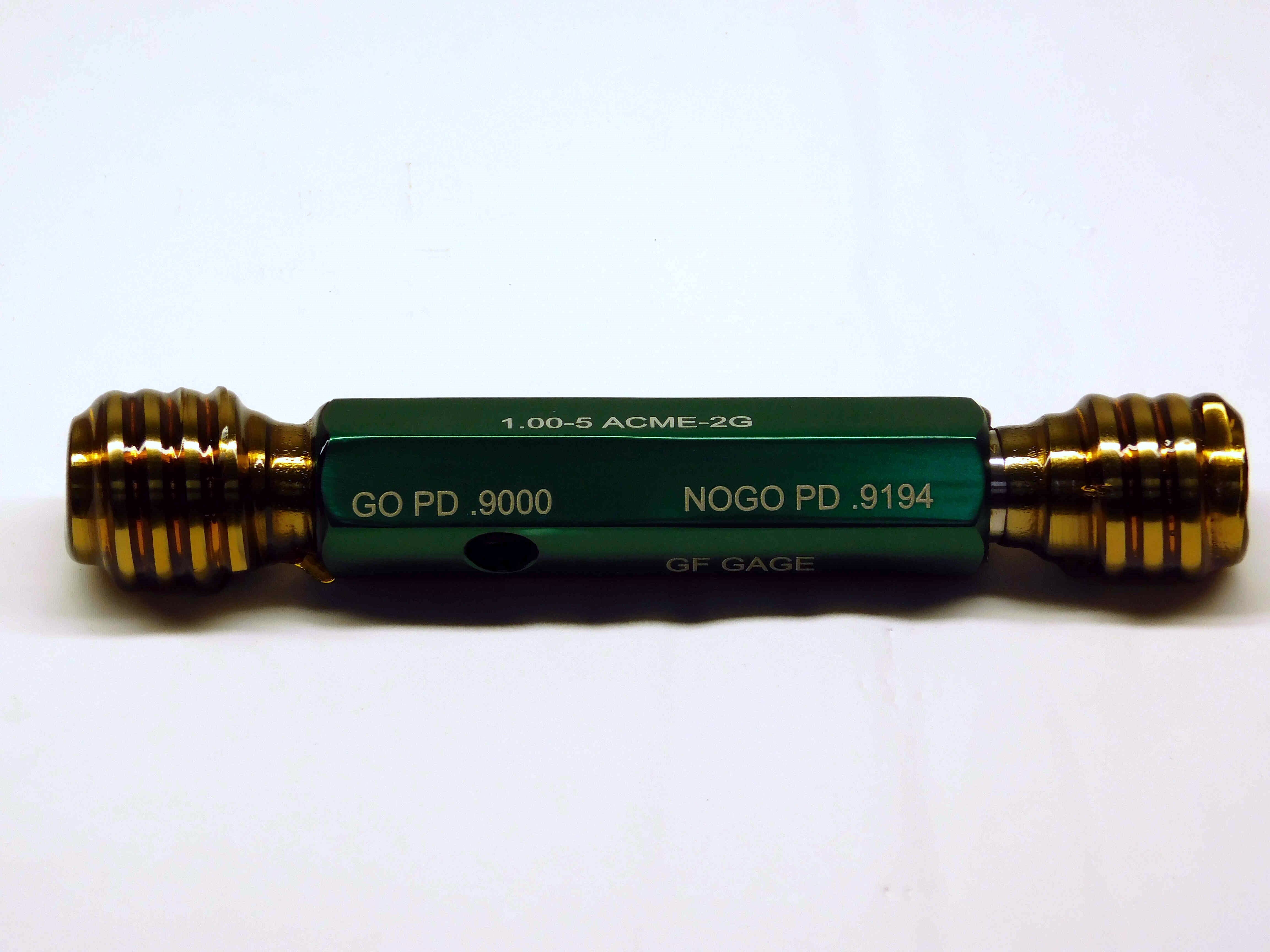
Example 2 (Single-Member):
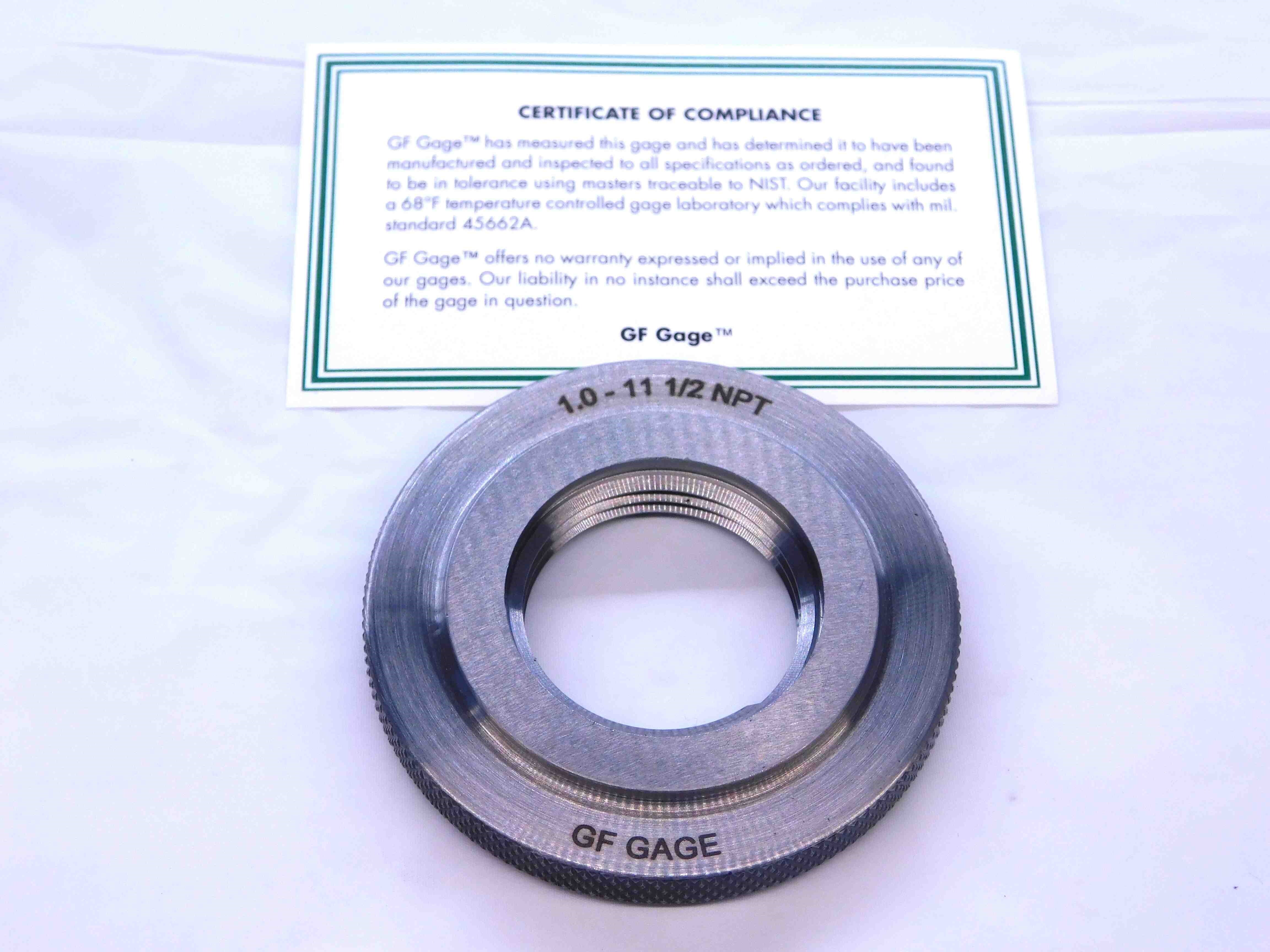
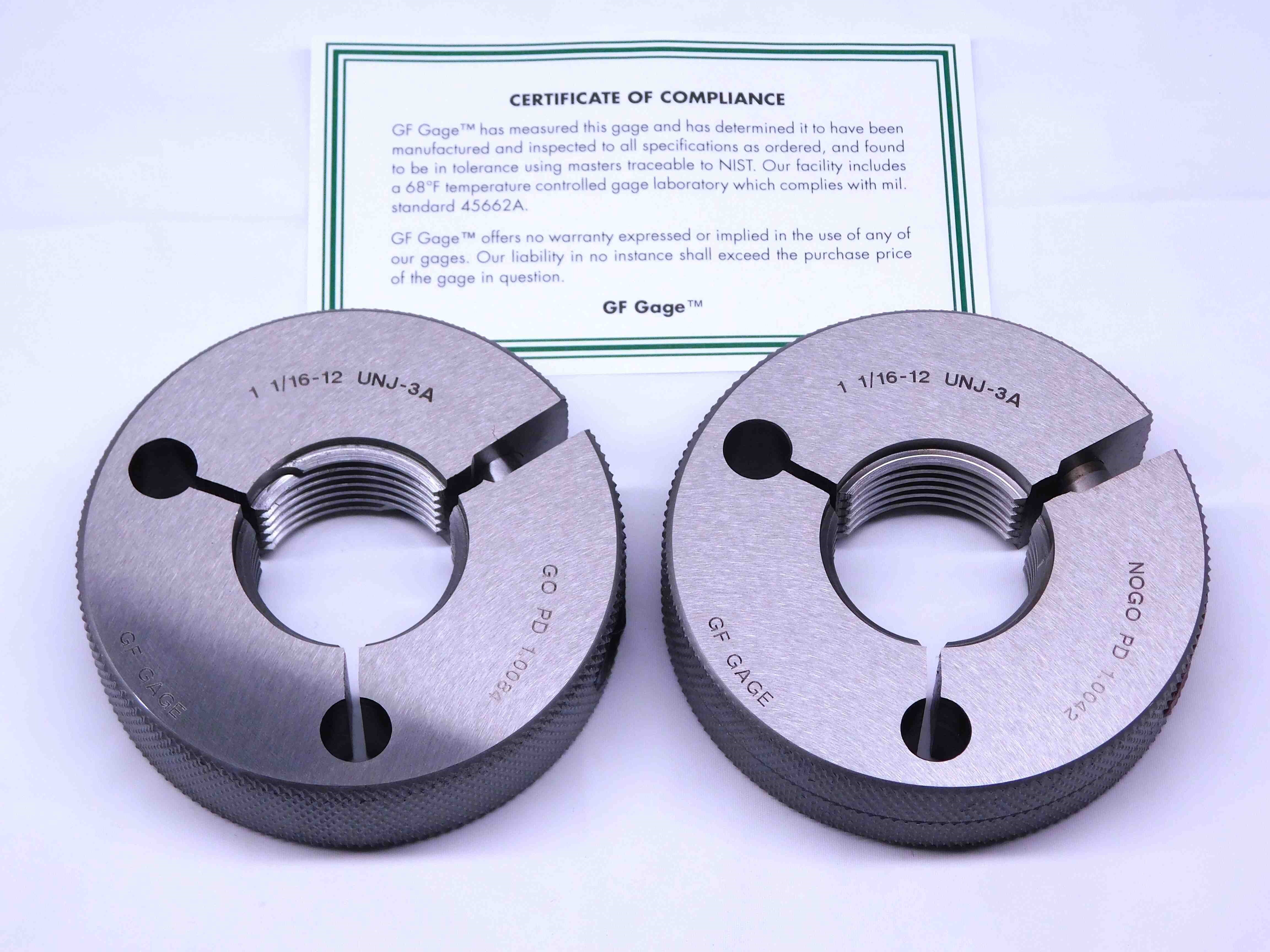
First picture: Place the gages in the center of the frame, with the "Go" ring on the left and the "No Go" ring on the right. If you are picturing just a single ring (such as a pipe gage), place the ring in the direct center of the frame. Orient the gages so that the size labeling is centered at either the top or bottom of the rings (whichever will be right-side-up). GF gages should always come with a "Certificate of Compliance". This should be placed behind the gage.
Second picture: A picture of the side of the rings, showing the edge wax and adjustment screws. If the rings are solid (non-adjustable), skip this picture.
Refer to the examples below:
Example 1 (Go & No Go):
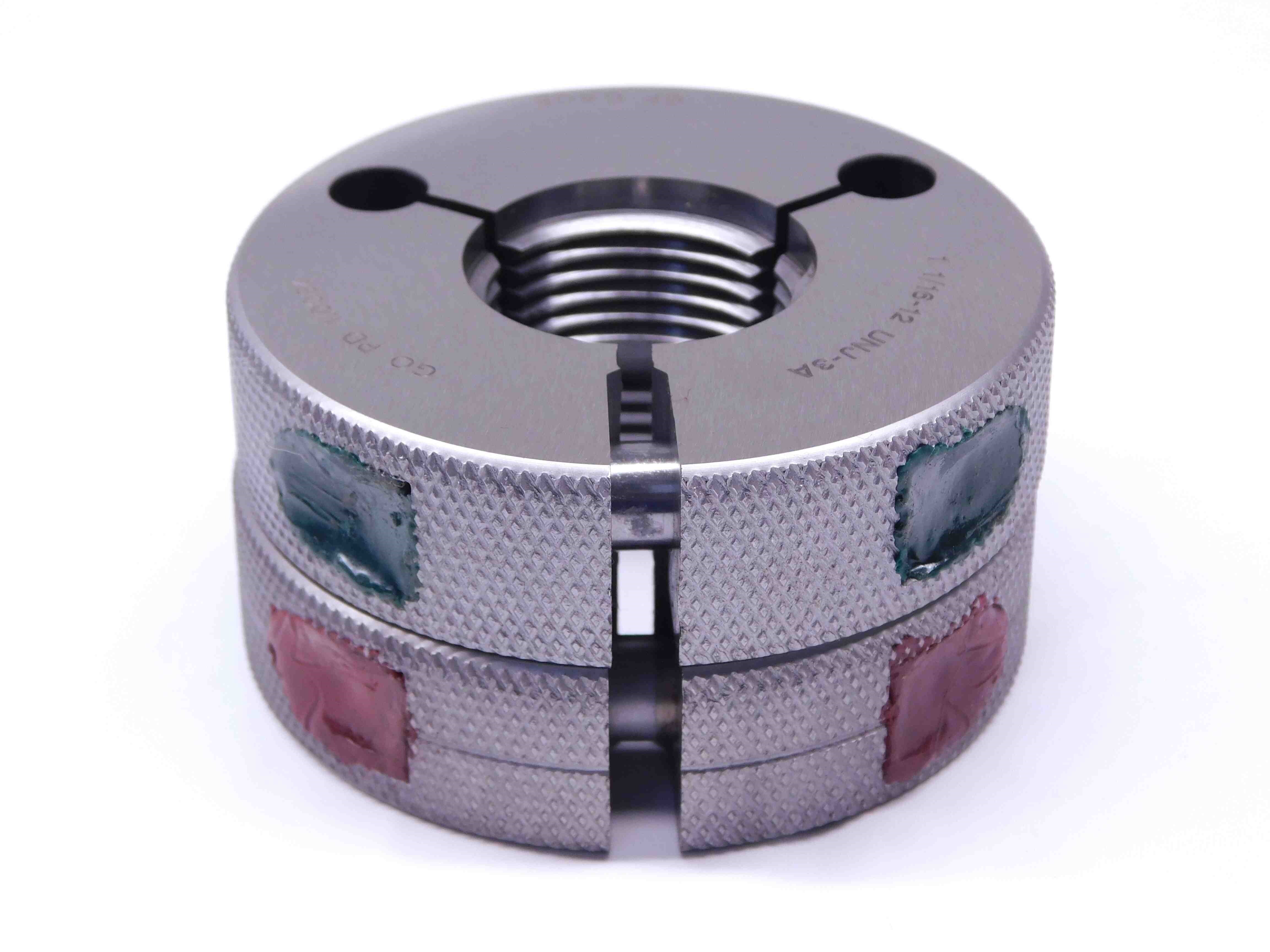
Example 2 (Single Ring):
