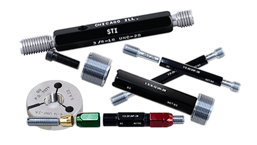
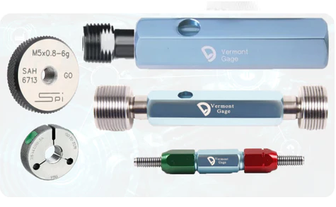
Thread gages are used primarily for checking the accuracy of internal or external threads on a machined part. There are a variety of different types of thread gages, which will be detailed later in this FAQ.
Any expired calibration stickers (or other stickers of any kind) should be removed from the gages. Plug gage handles and ring gage faces can be cleaned using WD-40 and a cleaning rag or Scotch-Brite pad, but do not use Scotch-Brite anywhere that there is labeling as it can cause the labeling to wear off. Threads should be cleaned using a wire brush, Scotch-Brite, or the wire wheel if they are especially dirty or rusted. Wipe the gages down with a dry rag after cleaning to remove any excess residue.
Waxing Thread Gages
Once they have been cleaned, most thread gages will be dipped in wax to help protect the threads from damage during storage/shipping. Gages that have thread damage will remain unwaxed so that the damage can be shown clearly in pictures.
Gage waxing is not necessarily done by the same person listing the gages. Your supervisor will provide additional training on gage waxing if needed.
*Click Here for NEW Thread Gages (MJ, LZ, VTG, GFG)*
Click here for info on how to upload pictures
There are many considerations which will affect how you picture thread gages. Be sure to read through this section in full before you start taking pictures in order to make sure you understand the proper way to picture each gage.
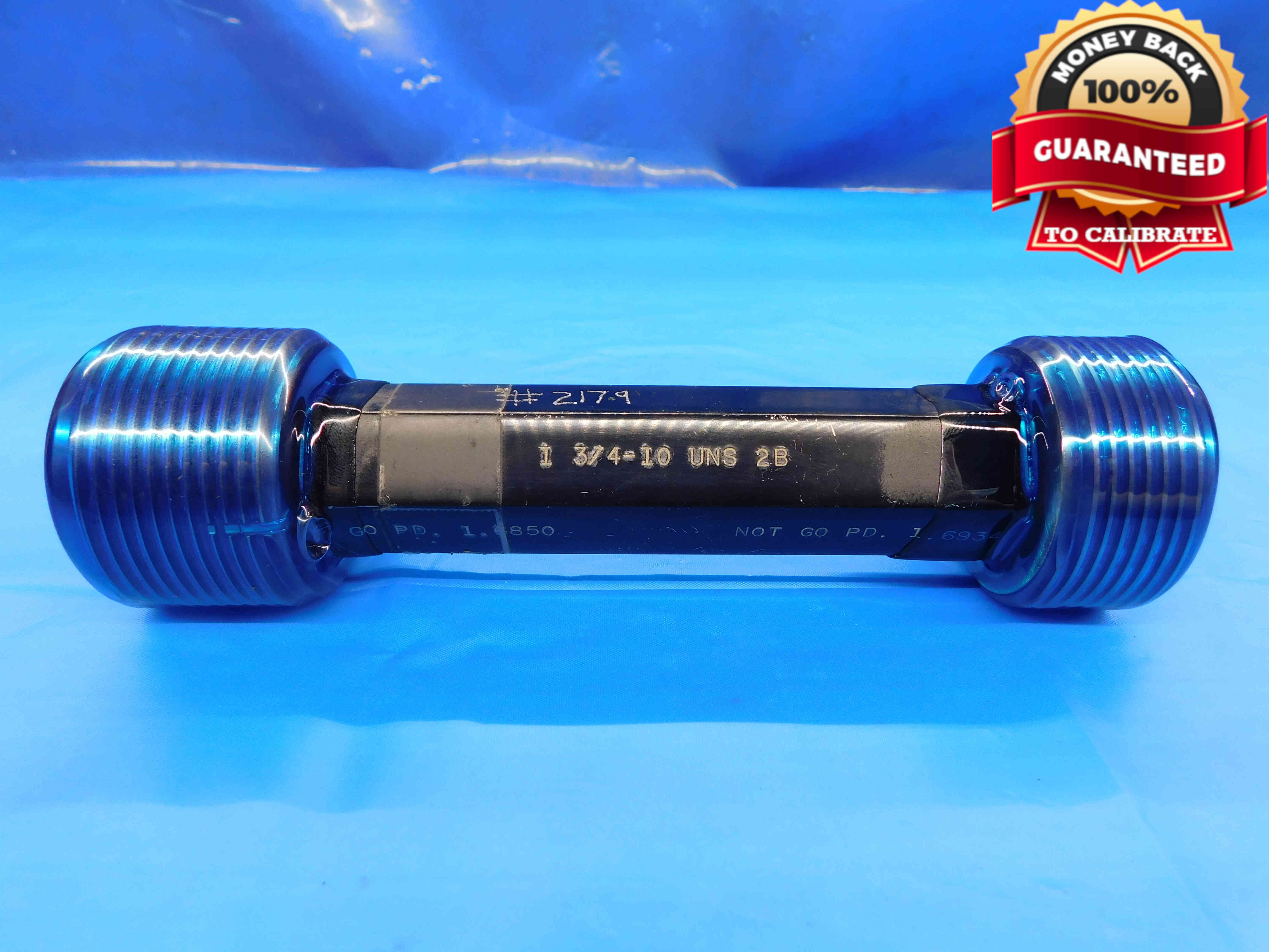
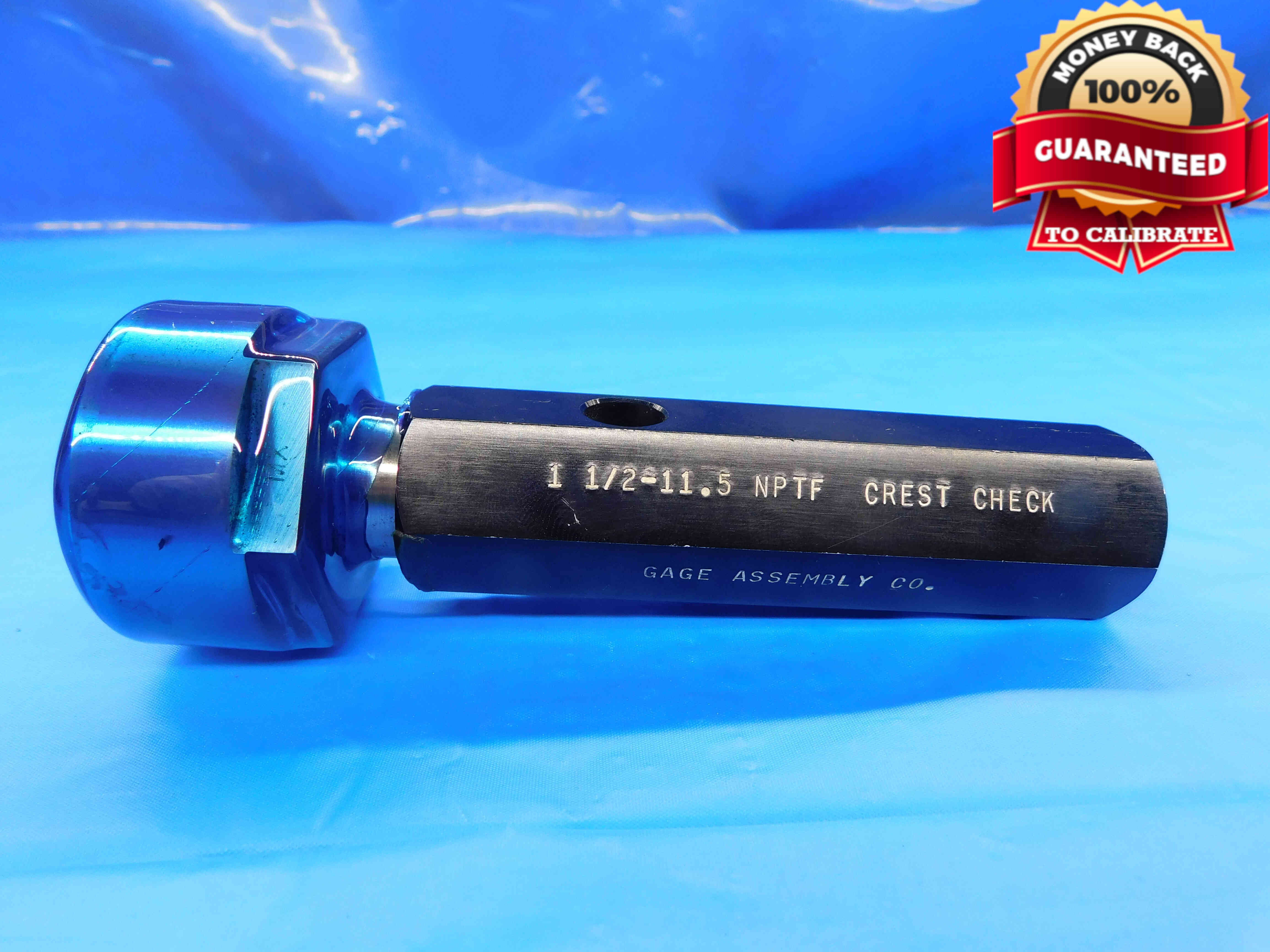
Thread plug gages will often require only a single picture. Position the gage horizontally in the center of the frame, with the Go member on the left and the No Go member on the right (UNLESS this will cause the labeling to be upside-down - this is uncommon, but gage handles are occasionally labeled in reverse). The size labeling on the handle should be visible in this picture, and ideally the P.D.'s should also be visible if possible. Any packaging or certifications should be included in this picture as well. Refer to the examples below:
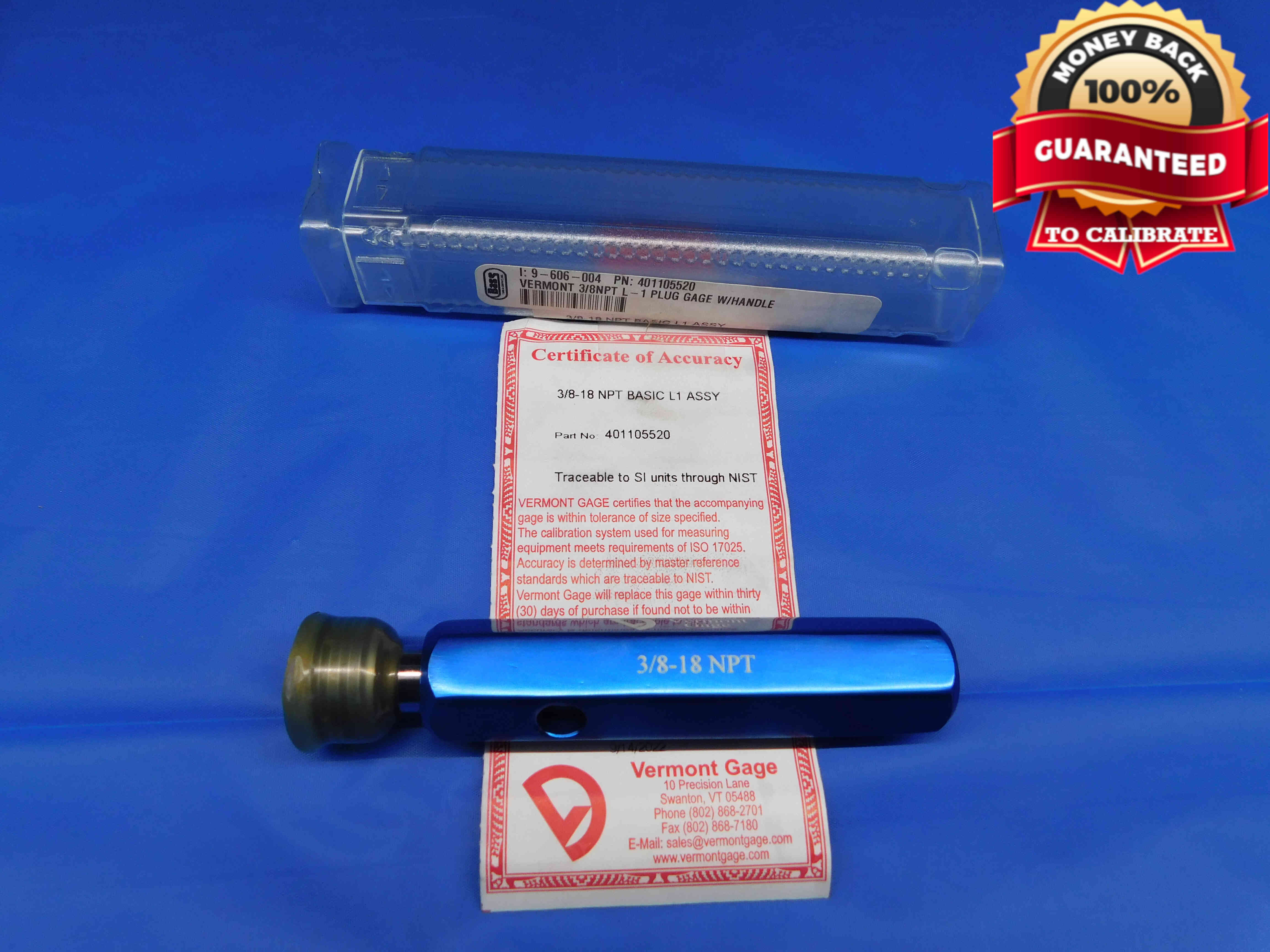
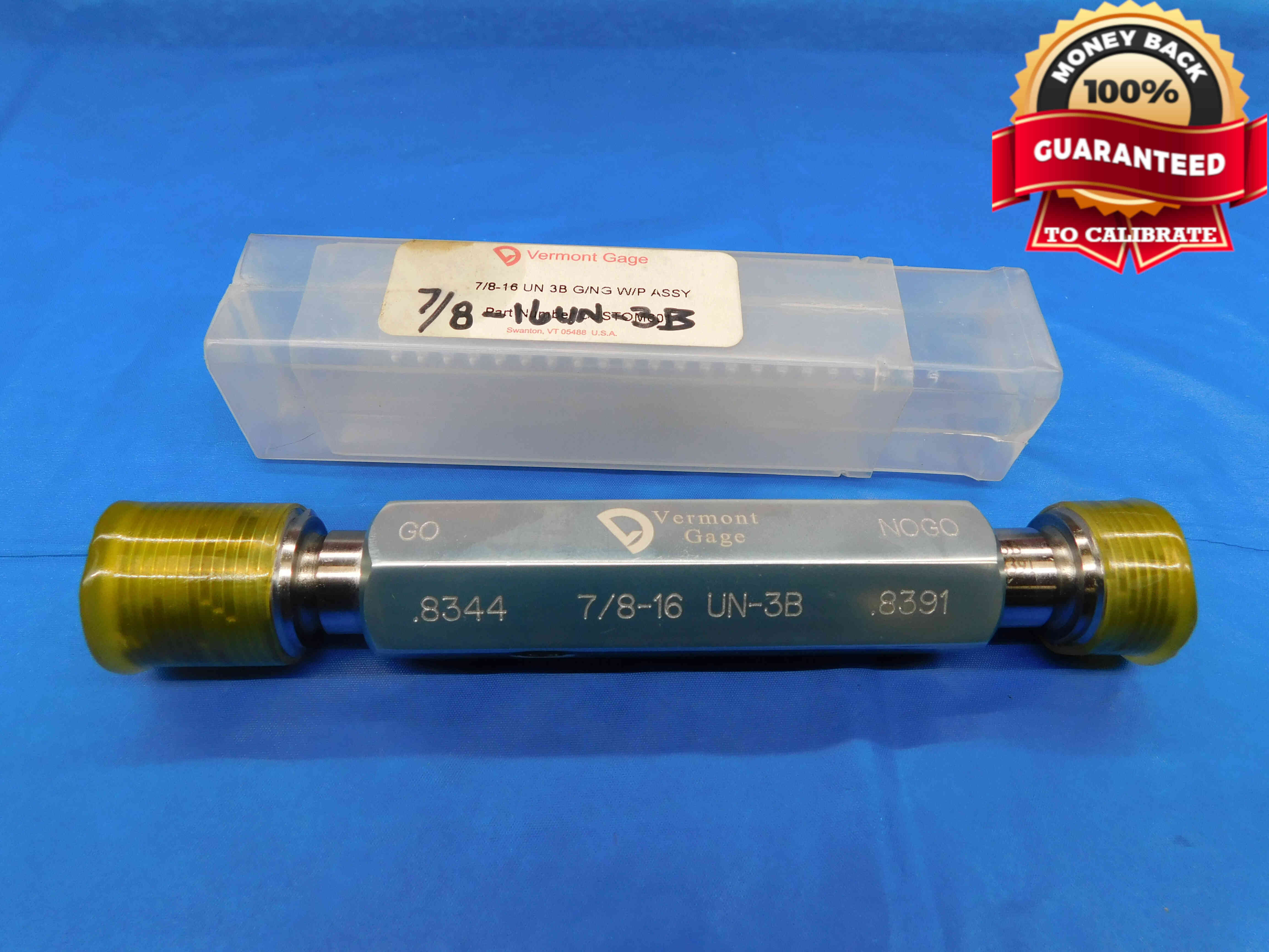
If the labeling is difficult to see on the handle, take an additional close-up picture which shows the labeling more clearly. Refer to the example below:
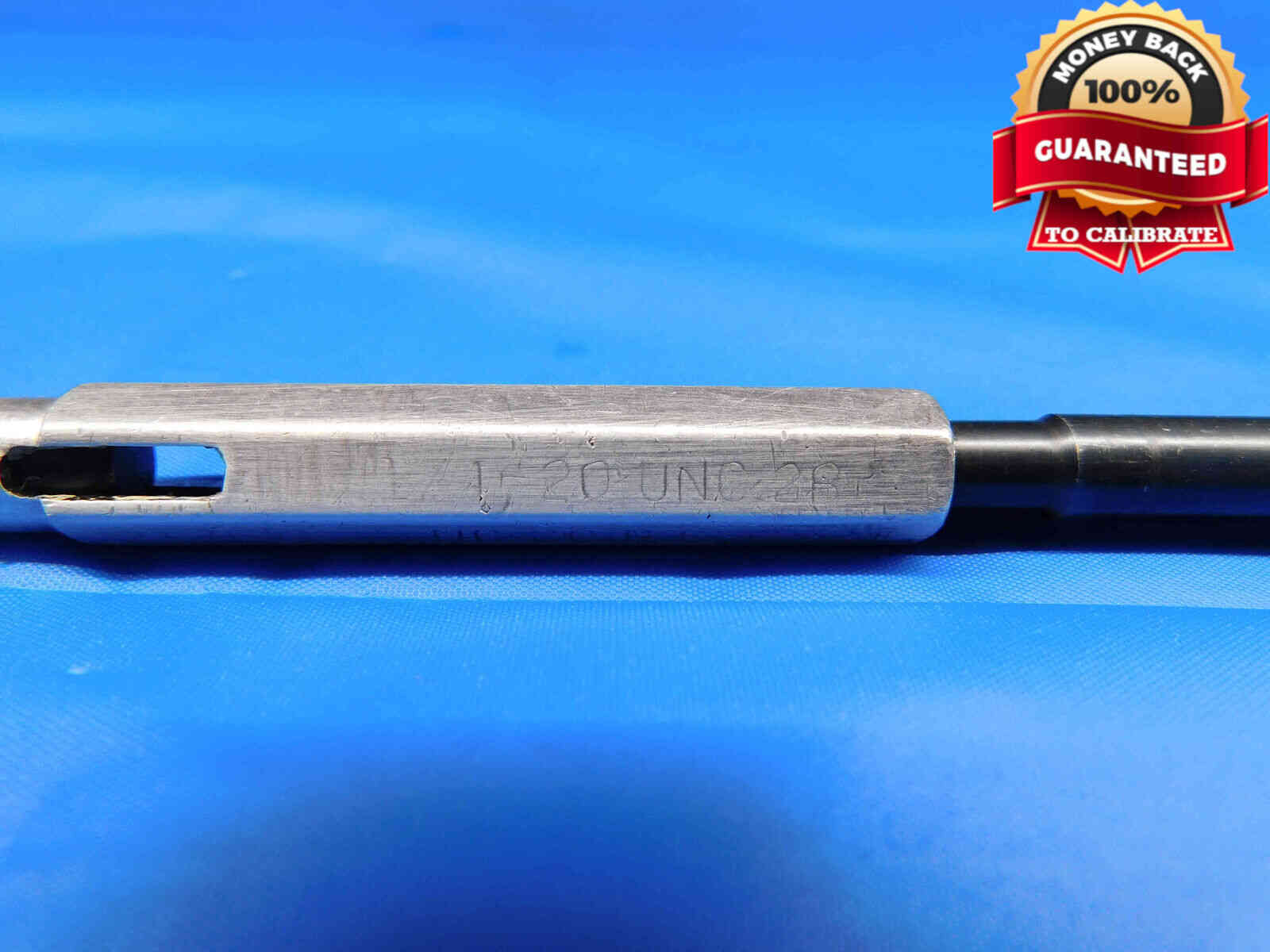
Extra long plug gages should have a tape measure included in the picture for scale. Refer to the examples below:
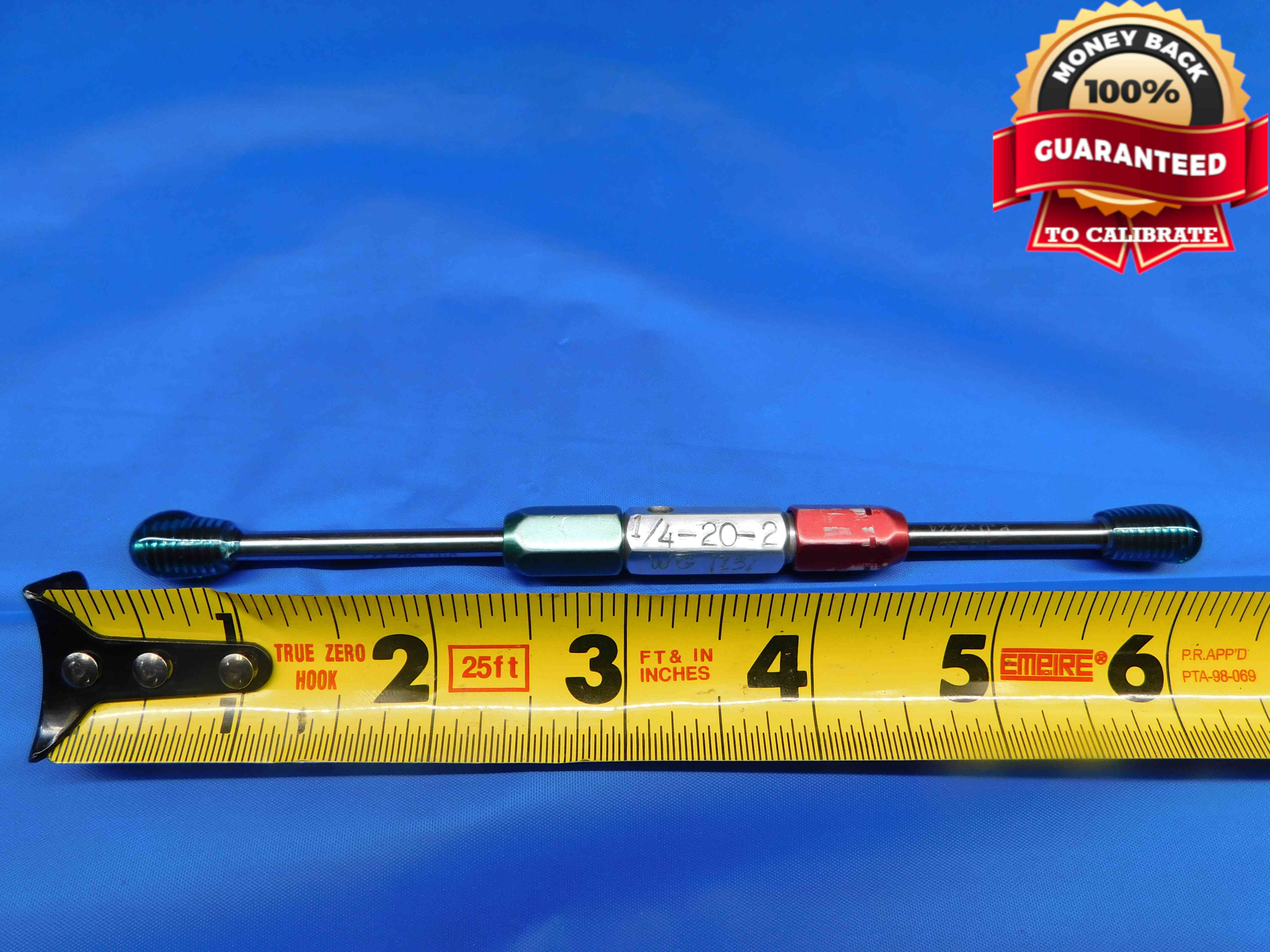
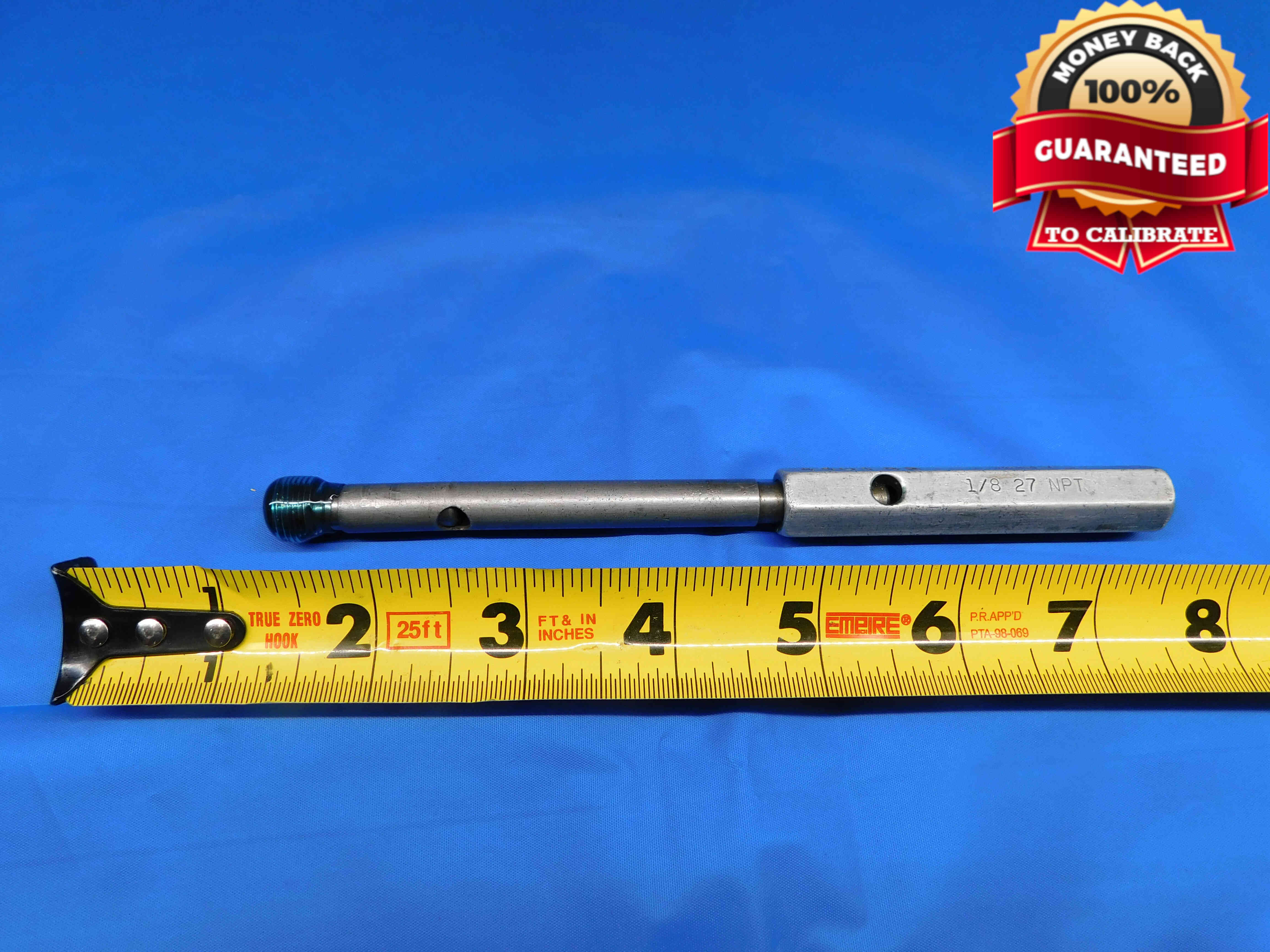
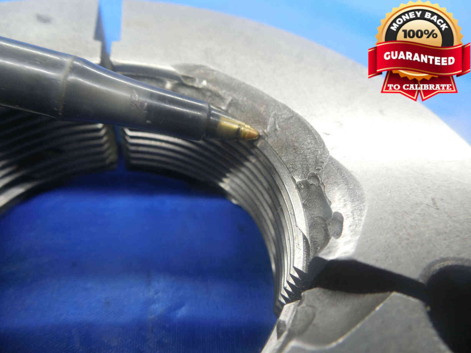
If there is any damage to the gage, especially to the threads, it must be clearly shown in an additional picture. Use a pen to point to the damaged area. Refer to the examples below:
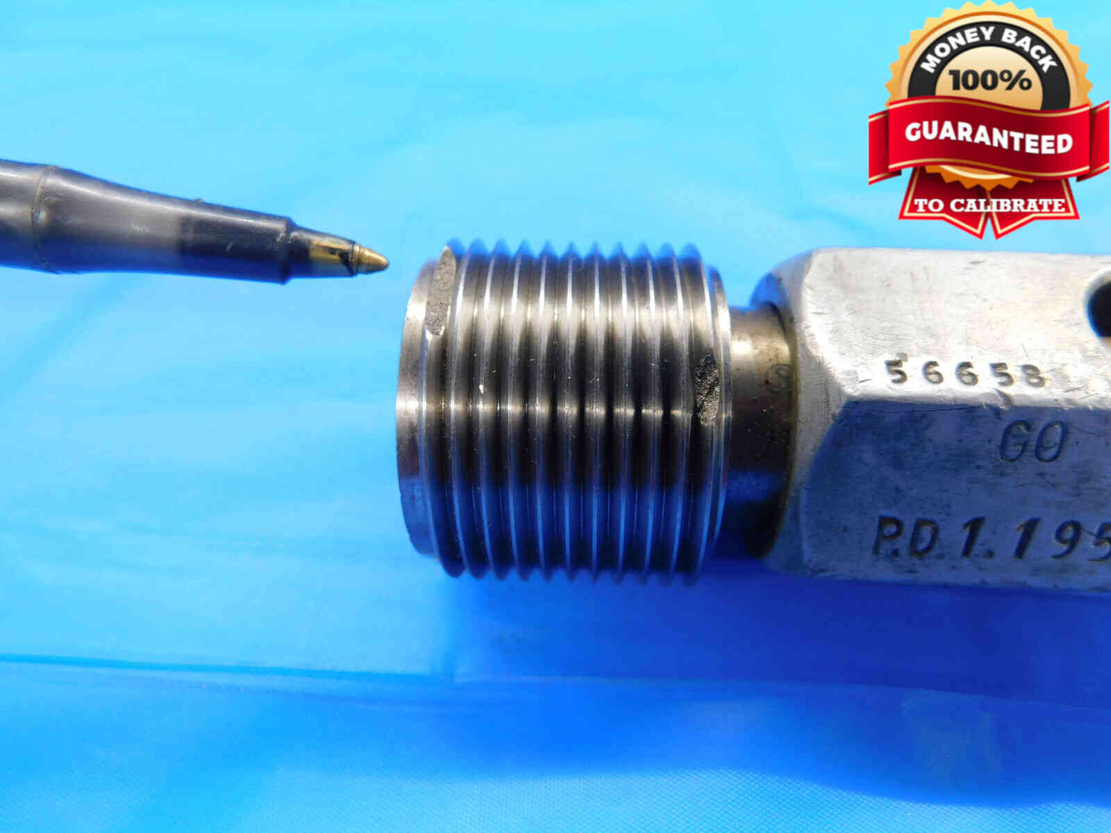
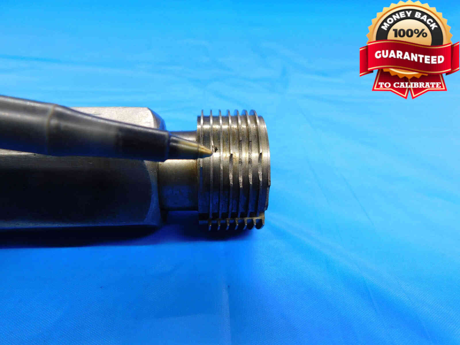
If you are picturing plug gage members without a handle:
Reversible Members are typically not listed by themselves, but if they are, they should be positioned horizontally in the center of the frame just like a normal go/no go + handle plug assembly. Reversible members are often unlabeled, so there should be an accompanying tag, case, or some other item which displays size information which should be included in the picture. If the member itself is labeled (which is uncommon), include a second picture which clearly shows the labeling.
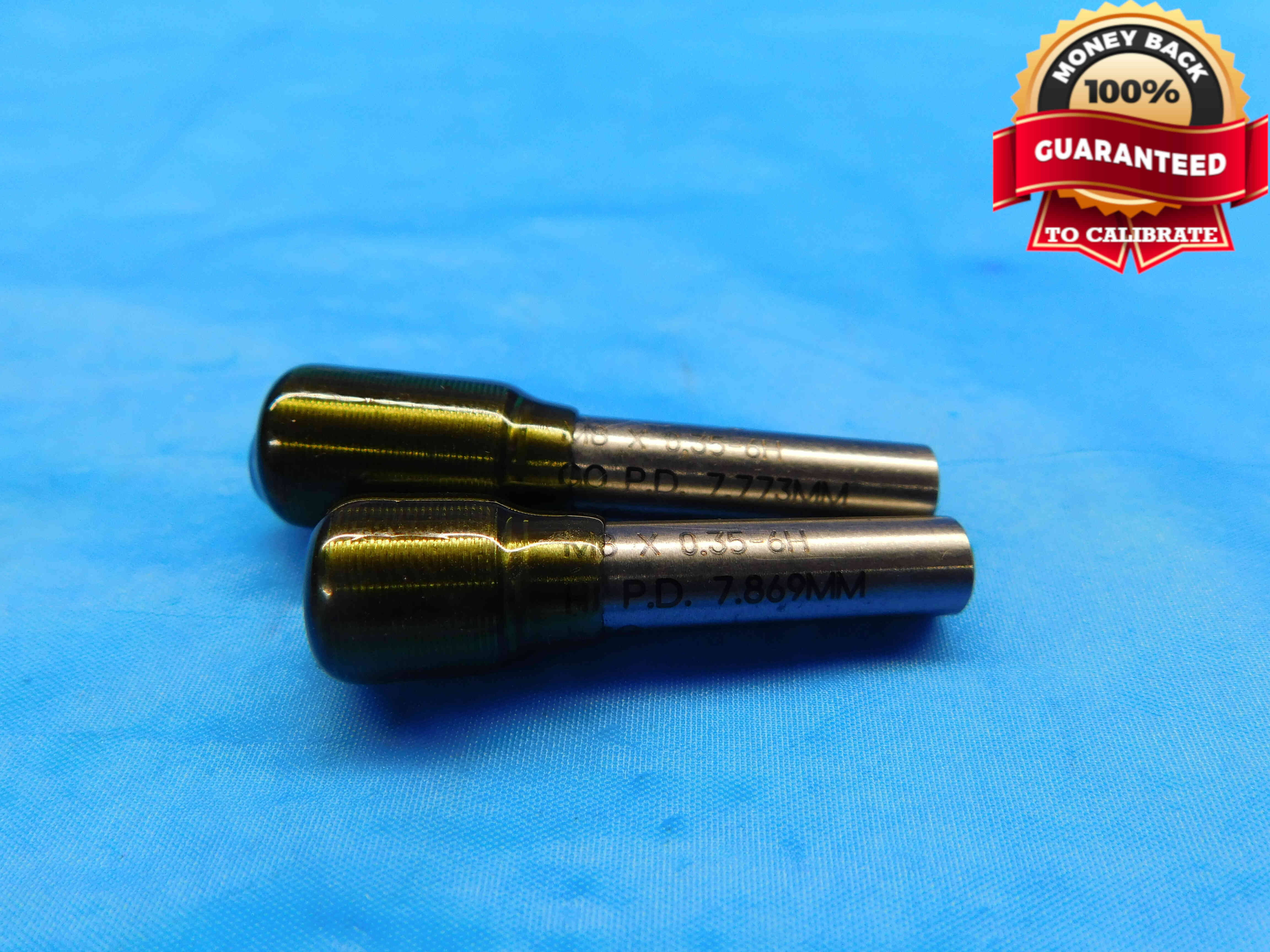
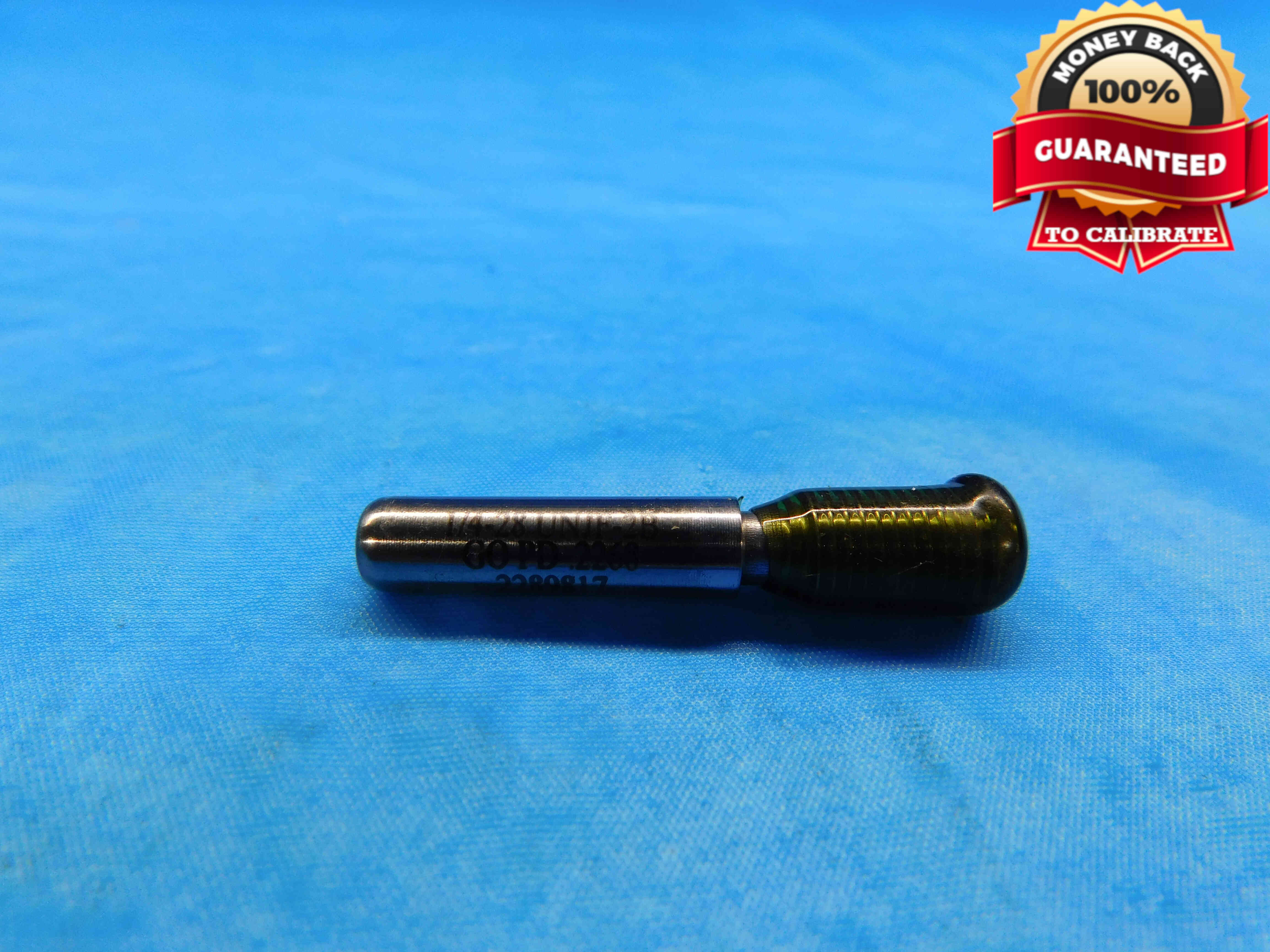
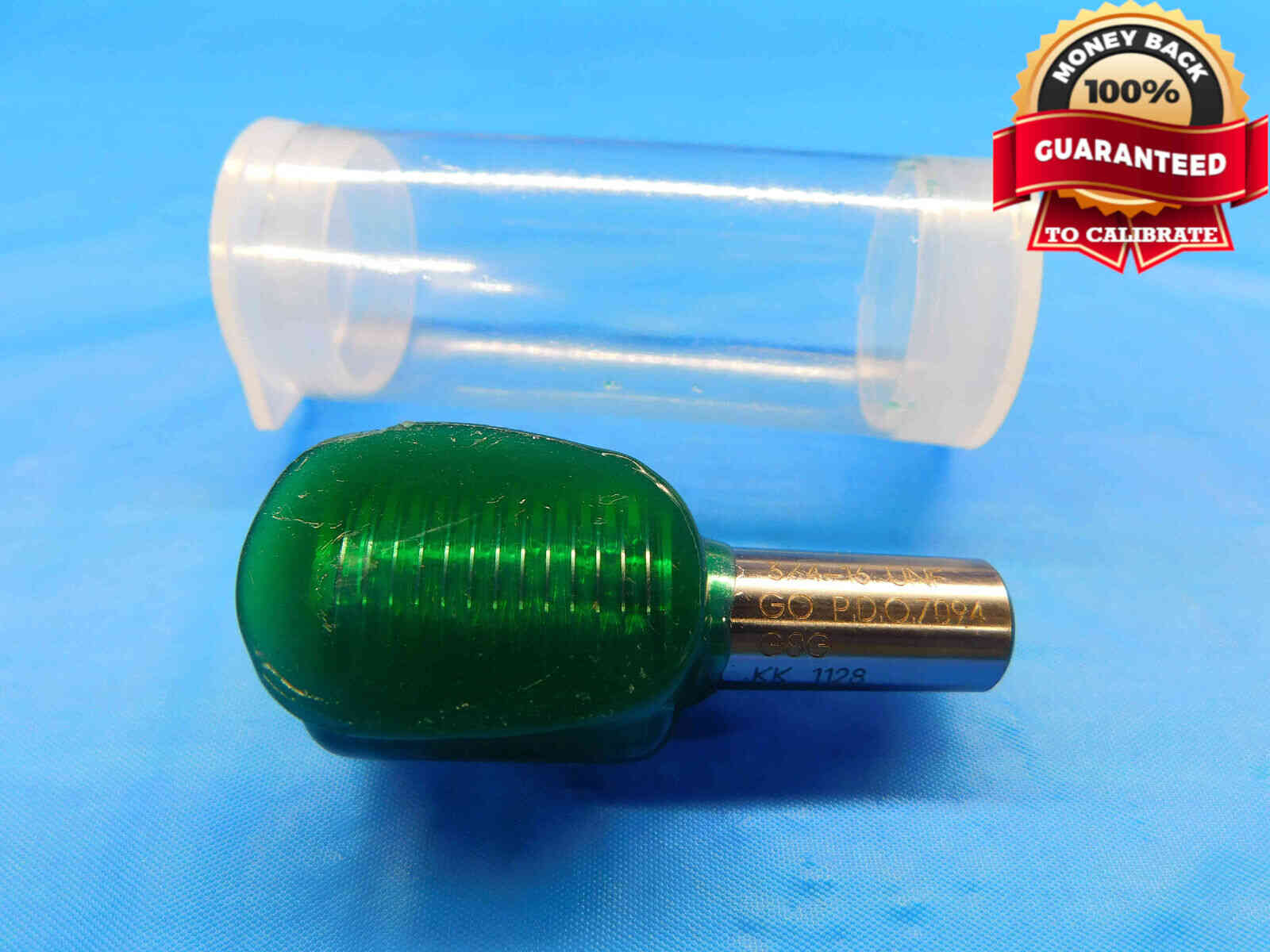
Taperlock Members should be positioned in the center of the frame, oriented in whichever direction allows the shank labeling to be readable (in other words, make sure the labeling is not upside-down). If there is no shank labeling, position the member(s) with the threads on the left side. If there is labeling on the face of the member, you will need additional pictures as described above. Refer to the examples below:
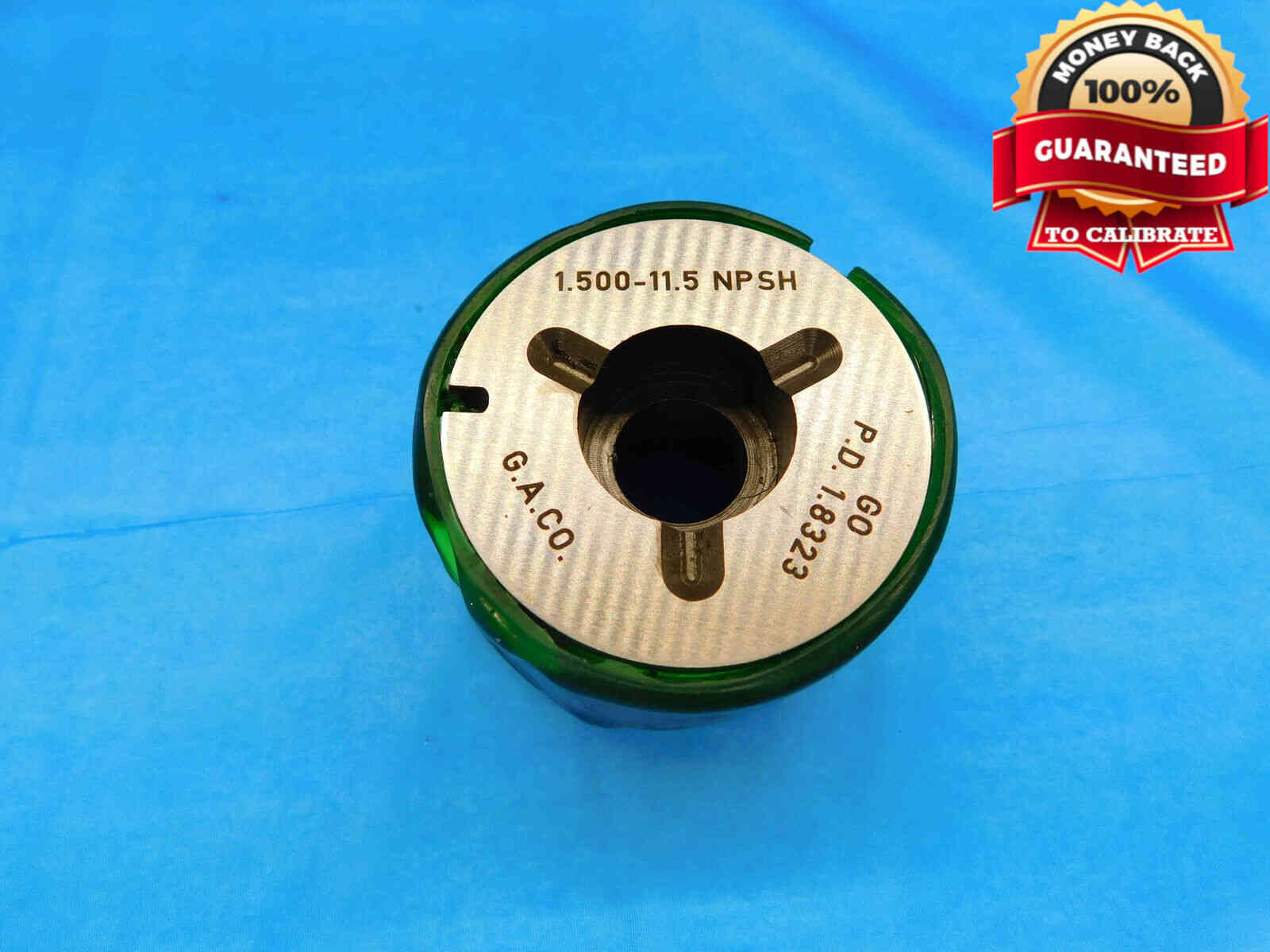
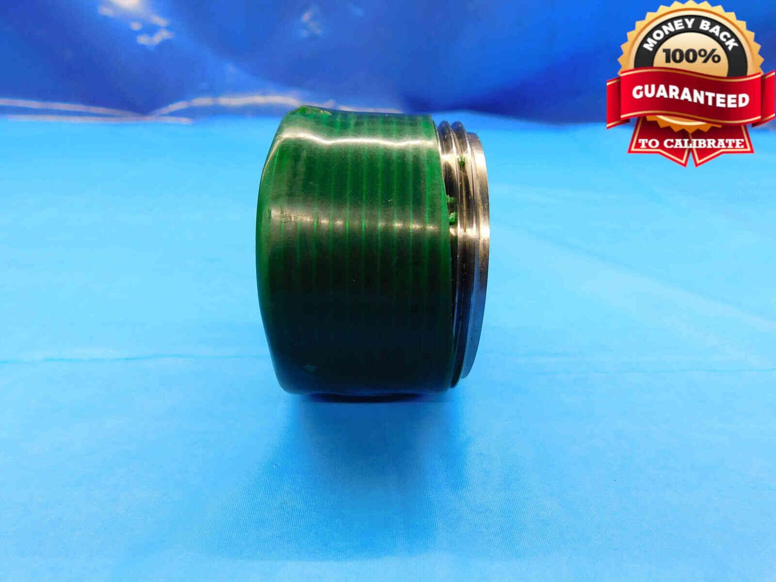
Tri-lock Members should be laid flat on their face in the center of the frame, with the primary size labeling visible and readable (i.e., not upside-down). A second picture should be taken of the gage on its side to show the condition of the threads. Refer to the examples below:
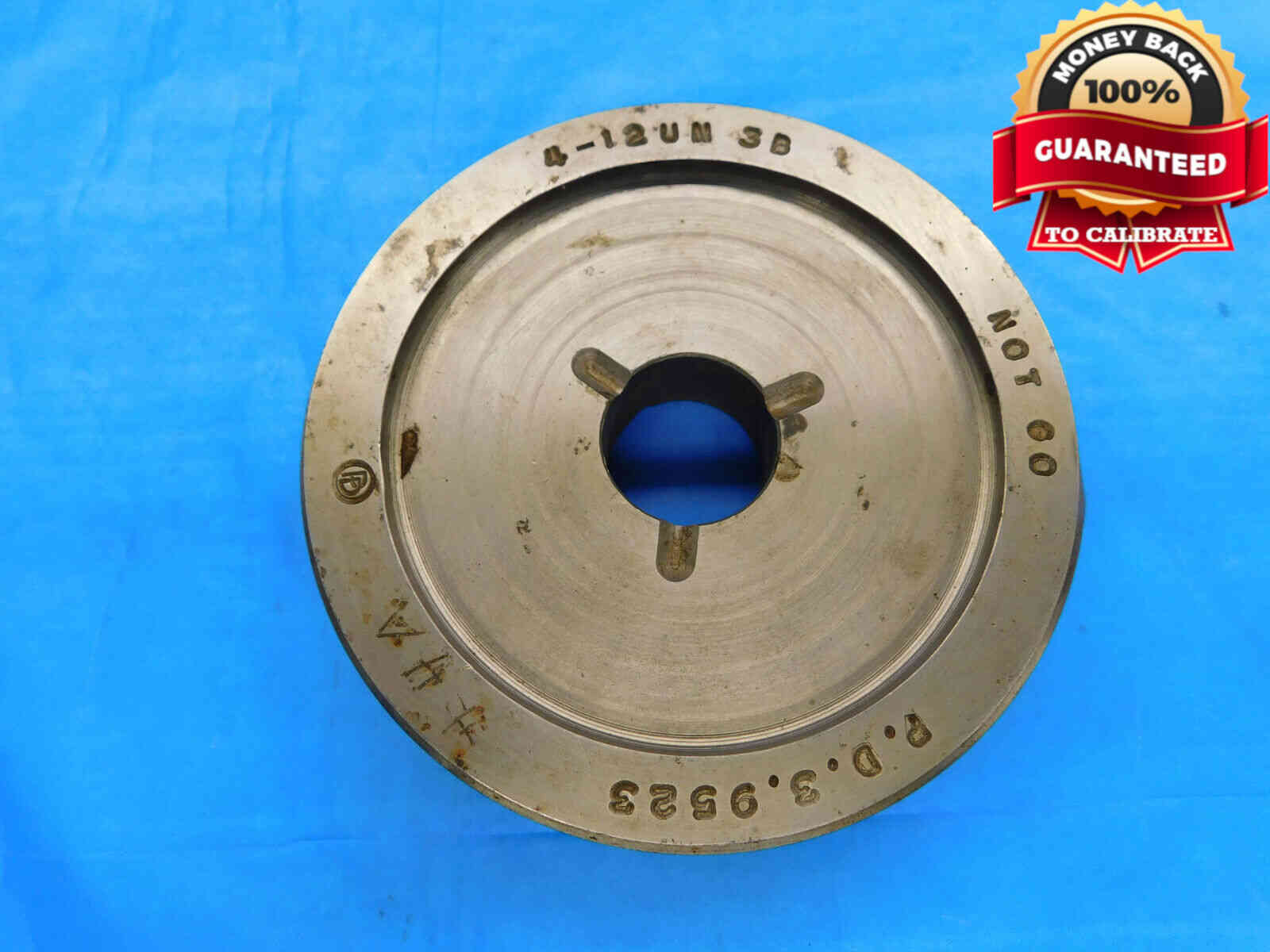
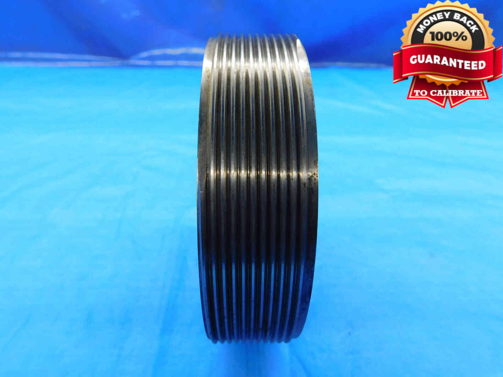
Ring gages will typically require two pictures. For the first, position the rings in the center of the frame, with the Go ring on the left and the No Go ring on the right (single rings are simply placed in the center of the frame). This picture should be taken from a 10 to 30 degree angle rather than straight down so that some of the threads will be visible. The rings should be oriented so that the size labeling is readable (i.e., not upside-down). Any packaging or certifications should be included as well. For the second picture (ADJUSTABLE RINGS ONLY), take a side-view shot of the rings which shows the edge wax and adjustment screws. Refer to the examples below:
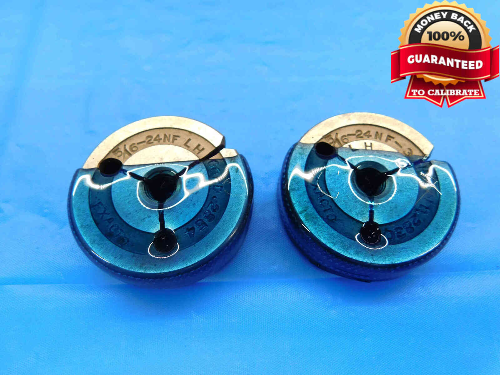
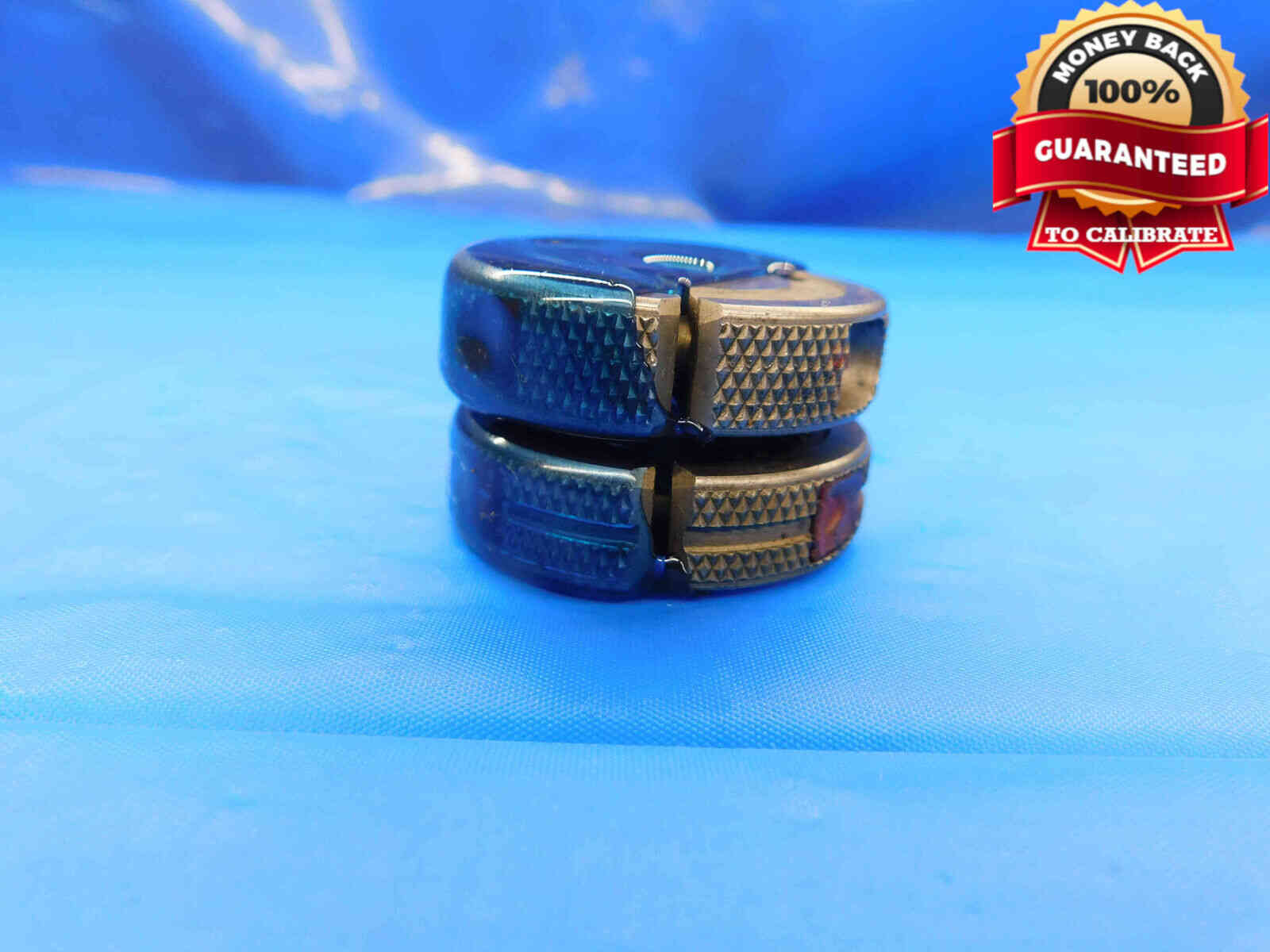
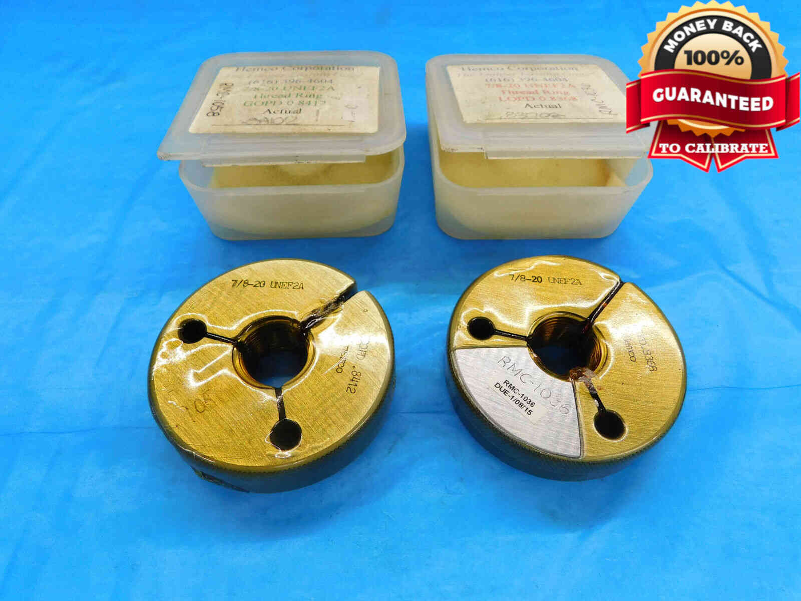
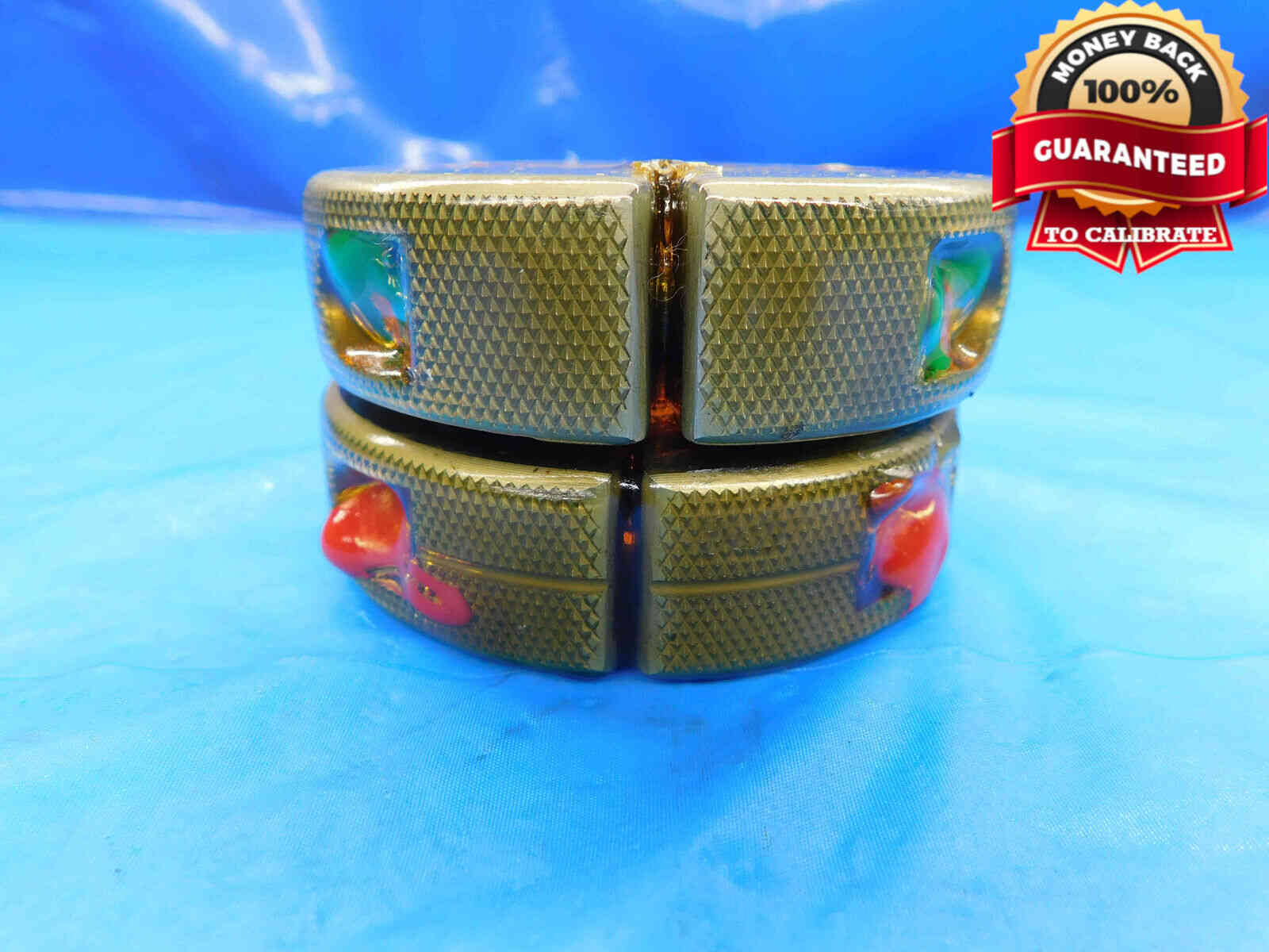
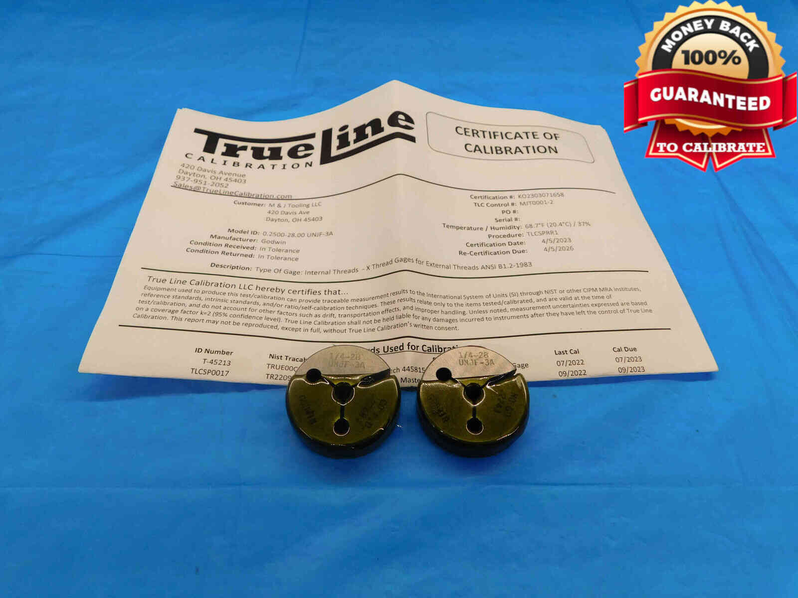
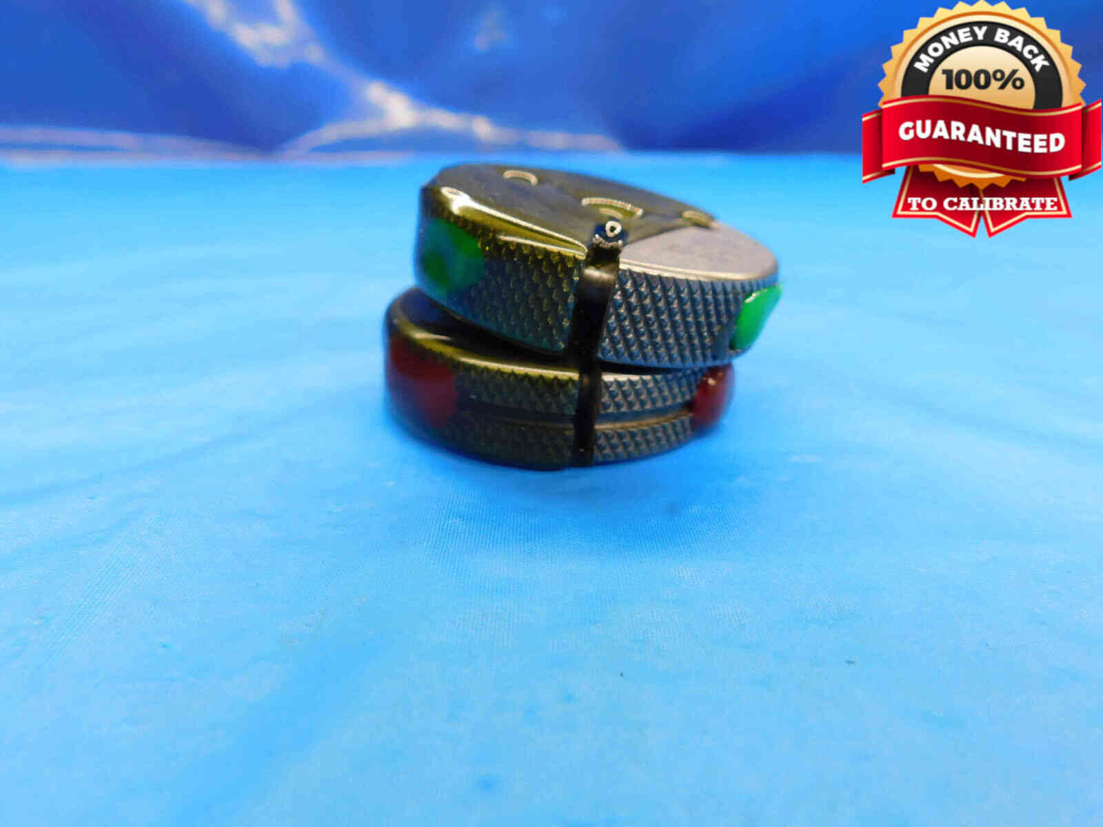
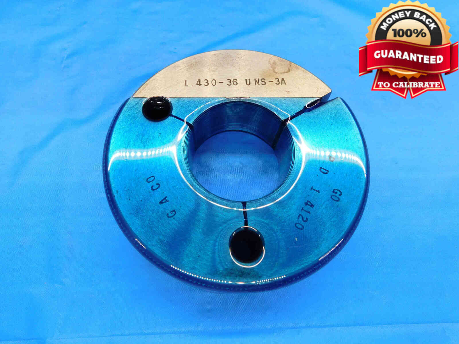
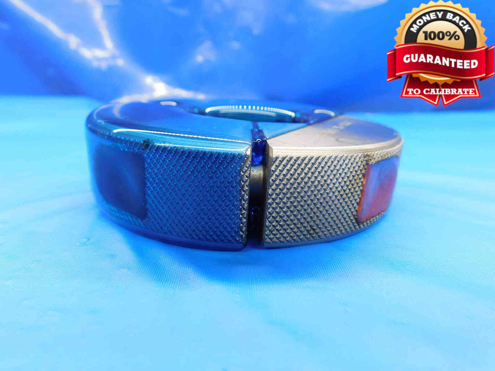
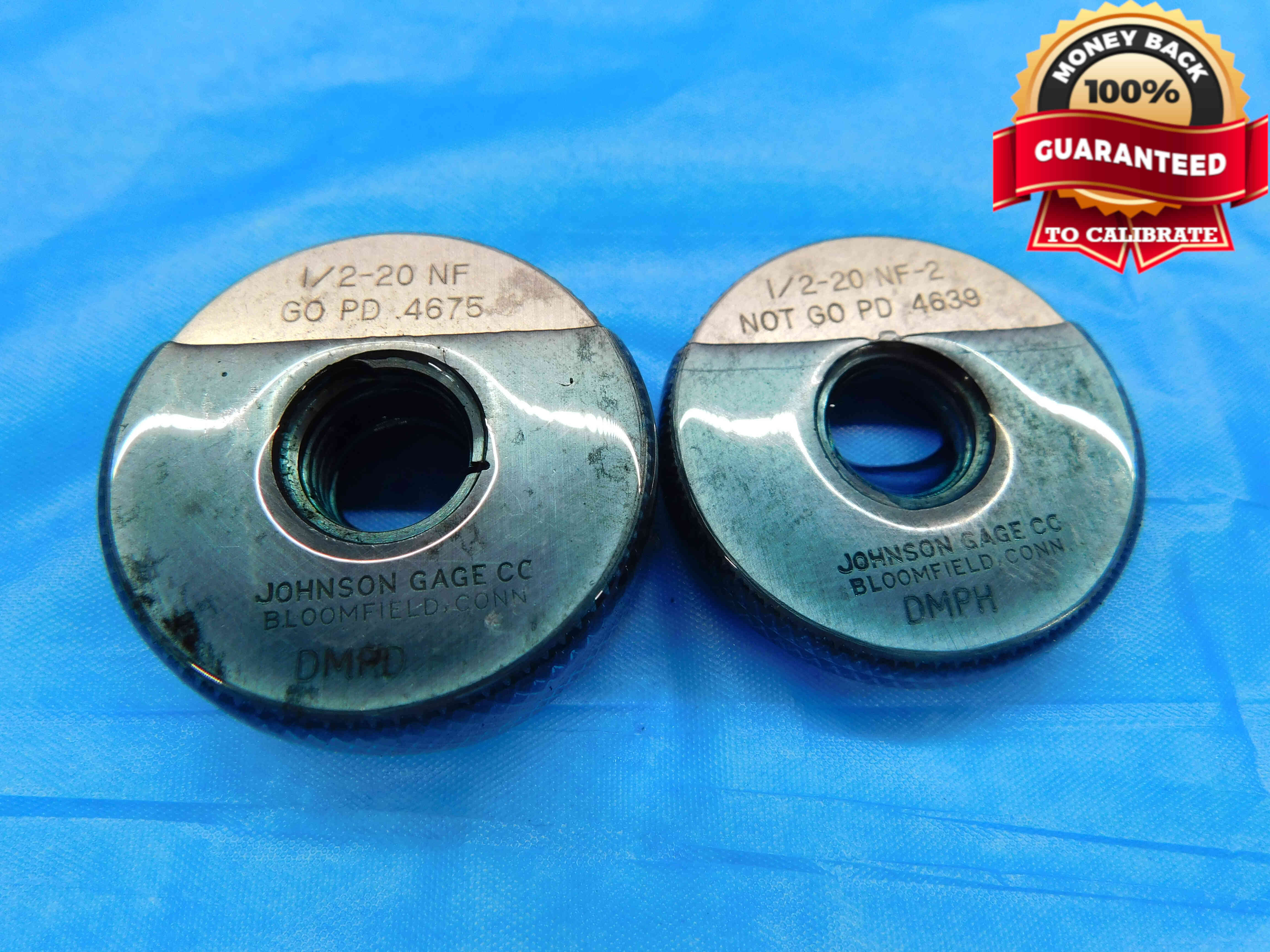
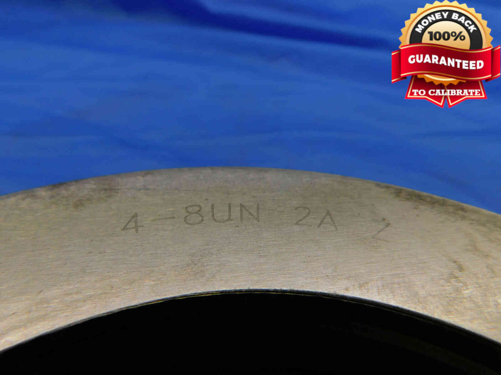
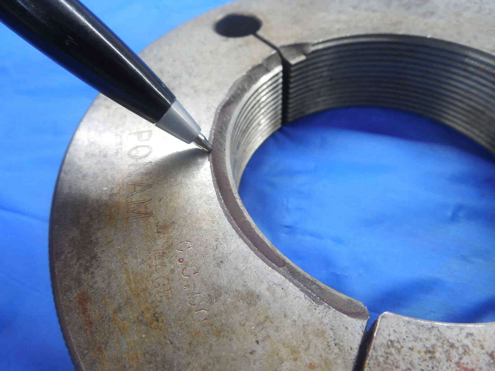
If the rings' labeling is not easily readable in the first picture (such as on very large rings where the picture is too zoomed out), additional picture(s) showing a clear close-up of the labeling will be needed. Refer to the example below:
As with plug gages, any damage to the gage, especially to the threads, MUST be clearly shown in an additional picture. Use a pen to point to the damaged area. Refer to the examples below:
Watermarking Pictures
You have probably noticed in the example pictures above that thread gage pictures are watermarked with a "Guaranteed to Calibrate" badge. Be sure to select the Gage watermark option when running your pictures through the Batch Image Tool.

The first thing you will need to do when listing a thread gage is select the Item Type from the dropdown menu at the top of each slot. There are five main categories of thread plug gages:
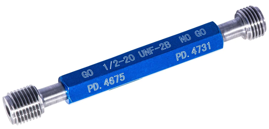

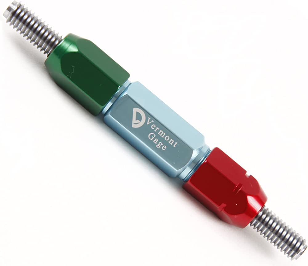
Working Thread Plug Gages (often just called Thread Plug Gages) are used for checking internal threads on a machined part. They consist of two threaded members which are classified as "Go" and "No Go", and are typically attached to a single handle (larger plug gages will often have separate handles for the two members, and especially large plug gages may even have multiple handles per member). If the thread being checked was machined correctly, the Go member will thread into the part, and the No Go member will not thread into the part.
Thread plug gages come in a few different styles, each with a different method of attaching the members to the handle:
Reversible

Reversible Plug Gages get their name from the fact that the members are symmetrical and can therefore be reversed in the handle if one end of the member is damaged / worn down. The handle has bushings (typically colored green and red for the Go and No Go sides respectively) which are tightened by hand or using a wrench to hold the members in place.
Taperlock

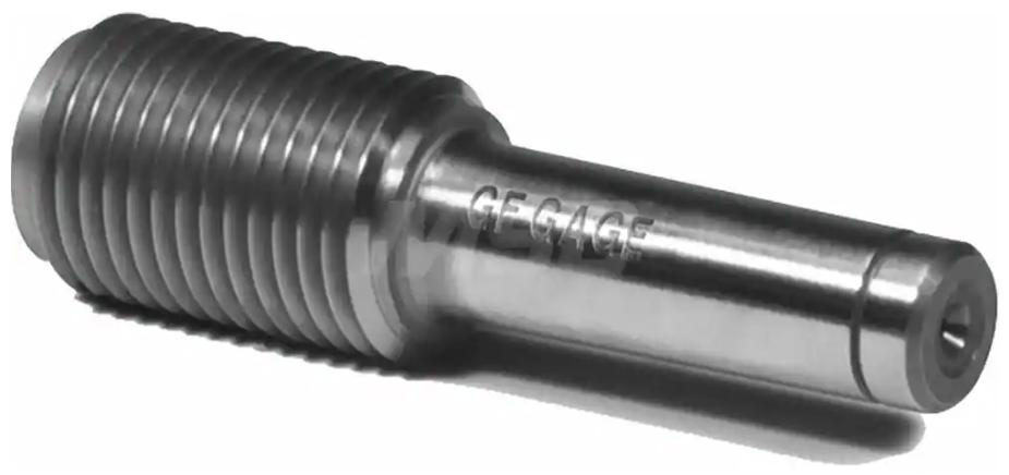
Taperlock Plug Gages, which are the most common style for most plug gages, have a tapered shank on the end of each member that is inserted into the handle and held in place by friction. The members can then be removed from the handle by inserting a tapered shim into a slot in the handle. The taperlock style is not available for larger gages and will typically not be seen on sizes larger than about 1.5" diameter.
Tri-Lock

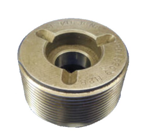
Tri-Lock Plug Gages have members that are affixed to the handle using a bolt, and locked in place by a three-point contact system. This is the standard style for larger plug gages (over about 1.5" diameter), but will sometimes be seen on smaller gages as well.
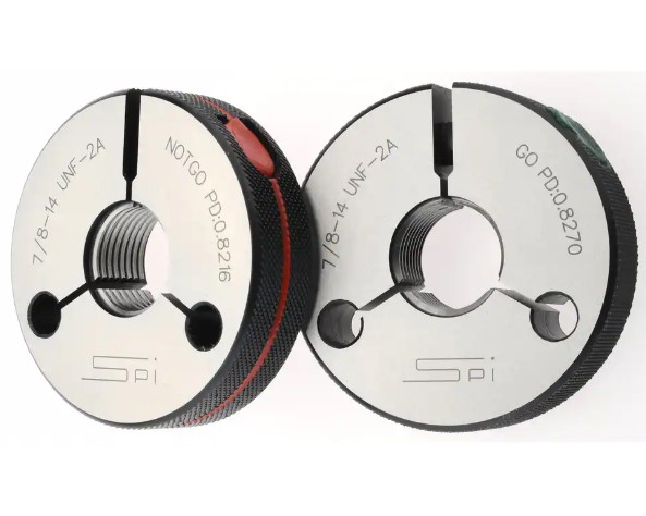
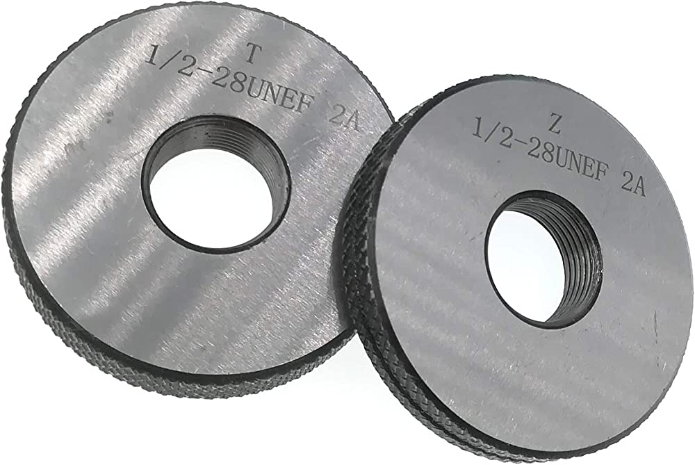
Thread Ring Gages are used for checking external threads on a machined part. Like plug gages, they consist of "Go" and "No Go", but unlike plug gages these will be completely separate rings and not attached by a handle or any other means (although ring gages do sometimes come with holders that hold both rings using screws). Similar to the function of plug gages, a properly machined part will thread into the Go ring, but not into the No Go ring.
Ring gages come in two different styles, solid and adjustable:
Solid

Solid Ring Gages are made from a single piece of solid material (typically steel). Because of this they are less likely to fall out of tolerance than adjustable rings and more resistant to damage from being dropped or mishandled. The downside to solid rings, however, is that they are also unable to be adjusted/re-set - meaning that once a solid ring gage is out of tolerance, there is typically nothing that can be done to bring it back into tolerance.
Adjustable

Adjustable Ring Gages consist of a split design with a set screw running horizontally through the ring. Minor adjustments can be made to this screw to slightly alter the size of the ring, allowing it to be re-set if it falls out of tolerance. Regular re-calibration is typically required due to these gages naturally going out of tolerance after being used many times.

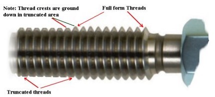
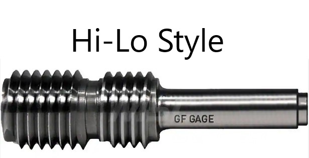
Setting Thread Plug Gages, unlike working thread plug gages, are not used to check machined parts, but are instead used for calibrating and re-setting adjustable ring gages. The members will typically consist of a full-form section and a truncated section. Some set plugs are entirely full-form, but these are relatively rare. Another less common style is the Hi-Lo setting plug, in which each member has two distinct sections corresponding to the lowest and highest ends of the gage tolerance.
Pipe Thread Plug Gages & Pipe Thread Ring Gages

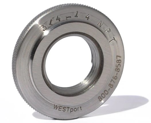
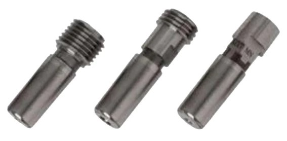
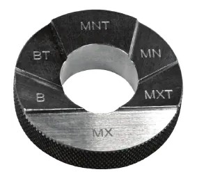
Pipe Thread Gages, which include both plugs and rings, are used for checking various types of threaded pipe fittings which each have their own distinct specifications. Some pipe gages are not threaded, such as the "6-Step" gages included in the images above, but are still categorized as thread gages since they are used for checking threaded parts.
Pipe gages will typically have a "P" somewhere in the class callout (such as NPT, ANPT, NPSM, BSPP...) and will fall into one of two categories:
Straight Pipe Thread Gages are functionally very similar to standard thread gages. They consist of Go and No Go members and will usually have an "S" somewhere in the class callout (NPSM, NPSL, NPSF...).
Tapered Pipe Thread Gages, as the name implies, are used for checking tapered threads. They consist of a single member and will typically have a "T" somewhere in the class callout (NPT, ANPT, BSPT...). All of the pipe gages shown in the example images above are tapered pipe gages.
Understanding Thread Gage Callouts:
Thread gages will be labeled with a standard callout, in which each part refers to a specific attribute of the thread. Several examples of thread callouts are given below, followed by explanations of what each part of the callout means:
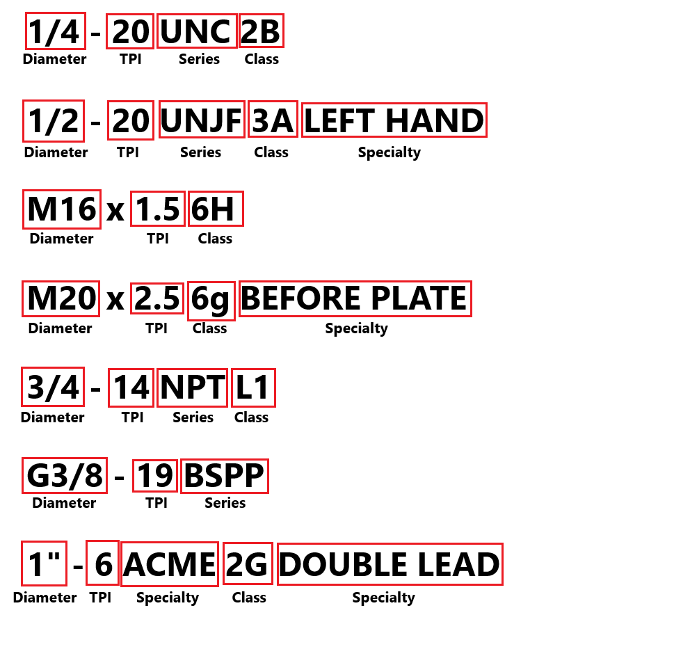
Diameter - The Outer Diameter / O.D. (plug gages), or Inner Diameter / I.D. (ring gages) of the thread. For metric gages, this is preceded by the letter "M" (such as M16 for a 16mm diameter). Some diameter sizes are described using numbers, which are listed below with their corresponding decimal equivalents:
#0 - .060" #5 - .125"
#1 - .073" #6 - .138"
#2 - .086" #8 - .164"
#3 - .099" #10 - .190"
#4 - .112" #12 - .216"
TPI - The number of Threads Per Inch, also referred to as Pitch. On a metric gage, this is the number of millimeters between each thread (but this is still referred to as "TPI" for listing purposes). Imperial sizes are often (but not always) written with a "-" between the diameter and pitch, and metric sizes are almost always written with an "x" between the diameter and pitch.
SERIES - This corresponds to the specific combination of O.D/I.D. and pitch. For example, 1/4 - 20 belongs to the UNC series, while 1/4 - 28 belongs to the UNF series. These are standardized thread sizes with set specifications. Special gages (such as a non-standard diameter/pitch combo like 1/4 - 26, or a "normal" size like 1/4 - 20 with non-standard pitch diameters) will typically be labeled with the series "UNS". Metric gages do not include a series, and for pipe gages, the series denotes the specific type of pipe fitting. For the purposes of listing, the series is included with the class. Some of the most common thread series are described below (this list is not all-inclusive):
UN (Unified)
UNC (Unified Coarse)
UNF (Unified Fine)
UNEF (Unified Extra Fine)
UNS (Unified Special)
***The series above all have "J" versions as well, which is a modified thread form used primarily in aerospace applications. The "J" always goes after "UN" (UNJ, UNJC, UNJF...). Metric gages can also have a "J" version, but for these the "J" goes after the "M" in the diameter (for example, "MJ16 x 1.5 6g")***
NPT (National Pipe Taper)
ANPT (Aeronautical National Pipe Taper)
NPTF (National Pipe Taper Dryseal)
NPS (National Pipe Straight - this series should always have a fourth letter which denotes the specific fitting type, such as NPSC = Coupling, NPSM = Mechanical, NPSL = Loose, etc.)
BSPP (British Standard Pipe Parallel, sometimes denoted with a "G" in front of the O.D./I.D.)
BSPT (British Standard Pipe Taper, sometimes denoted with an "R" in front of the O.D./I.D.)
CLASS - This refers to the Tolerance of the thread, or in other words how close the actual measured size is to the labeled size (as it is impossible for a gage to truly measure EXACTLY the listed size - it will always be within a very small acceptable limit on either side). Not all gages will be labeled with classes. The most common classes are listed below (this list is not all-inclusive):
Imperial Working Plug Gages - 1B, 2B, 3B
Imperial Ring Gages & Setting Plugs - 1A, 2A, 3A
Metric Working Plug Gages - 6H, 5H, 4H, 6G (NOTE: Capitalization matters)
Metric Ring Gages & Setting Plugs - 6g, 5g, 4g, 6h (NOTE: Capitalization matters)
ACME Gages (Plugs & Rings) - 2G, 3G, 4G, 2C, 3C
NPT/NPTF Gages (Plugs & Rings) - L1, L2, L3, 6-Step
SPECIALTIES - There are many different special properties that a thread gage can have. The most common are described below (this list is not all-inclusive):
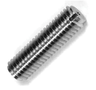
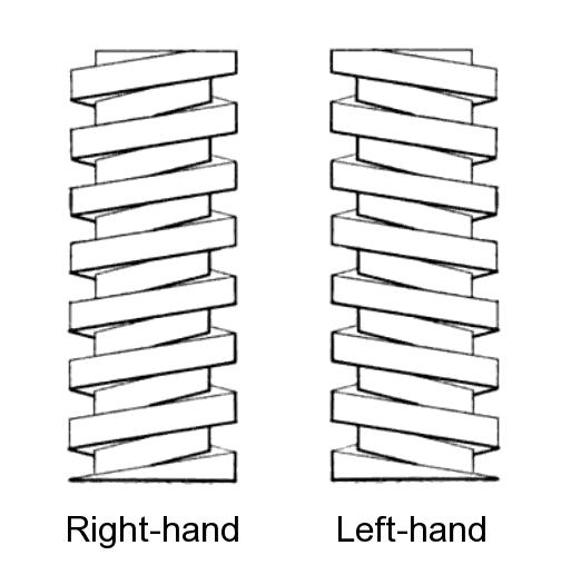
Left Hand - Threads that travel in the opposite direction from a standard right-hand thread, as shown in the image below:
Before Plate / Pre-Plate - An oversized (plug) / undersized (ring) gage used for checking a part that is going to be plated with chrome or some other material. The part would then be checked again with a standard thread gage once plating is complete.
"Special" / "MOD" - Gages are sometimes custom-made with non-standard specs. These will often be labeled with words such as "special" (sometimes abbreviated SPL) or "modified" (often abbreviated MOD).
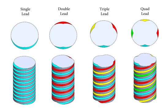
Multi-Start/Lead - A gage which consists of two or more intertwined threads running parallel to one another, such as in the image below:
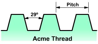
ACME - A thread form with a lower profile angle (29 degrees vs. the standard 60) and a flat crest, which is primarily used in heavy load work. This will sometimes be notated in the thread callout with "NA". Stub ACME is a variation with a shallower thread height, often notated as "SA".
Trapezoidal - A 30 degree thread form which is very similar to ACME. Trapezoidal threads are more common in Europe, while ACME is used more in the US. Trapezoidal threads are usually metric, and will have a "TR" at the beginning of the callout similar to how standard metric callouts use "M".
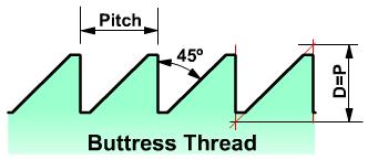
Buttress - An asymmetrical thread form which is square on one side and angled on the other, designed to handle extremely high axial thrust.
STI - Also referred to as Helicoil or Wirecoil, these are oversized plug gages used to check parts that use special thread inserts.
Shop-Made - Machine shops will sometimes make their own thread gages, often for cases in which they only need to check a small number of parts and can't justify spending a lot of money on a professionally-made gage. These gages MUST be described as Shop-Made in the title. They will often not be labeled with a class or pitch diameters.
Spiralock - A special type of gage made exclusively by the company Stanley, these are unique plug gages that consist of three members instead of the typical two, with the third being the "Hi-Limit Ramp" gage. They are often labeled with "SPL" which might be confused for "Special".

Almost all gages (tapered pipe gages being the primary exception) will be labeled with Pitch Diameters for both members. The exact definition of a pitch diameter is somewhat complicated, but you can think of it as the diameter of the thread at the approximate midpoint between the crest and root. Every thread size has a set of "standard" P.D.'s, but gages can also be custom-made with special P.D.'s. Because of this, it is extremely important that P.D.'s are entered accurately. When listing a single-member gage, simply leave the P.D. blank for the member that is not present. For gages with no P.D.'s, leave both blank.
The "Filler" section is used to add other relevant information to the title which is not covered by the other sections. Thread gages will typically not require any fillers, but you may occasionally need to include extra descriptors for some gages such as "Extra Long", "TiN Coated", "Chrome", "Carbide", and so on.
Keep in mind that titles have a maximum of 80 characters, and if you are adding fillers you may need to manually remove some less-important information from the title in order to make room. Contact your trainer if your title is over 80 characters and you are not sure what to remove.
One brand to look out for is Vermont Gage, often abbreviated as VTG. These gages are more sought after due to their perceived higher quality and will often be worth more. If the gage does not have a labeled brand, click the "Unlabeled" button to the right of this cell. Make sure that this cell is not left blank, or the listing will not upload properly. Note: Items are often labeled with the country of origin (USA, China, Japan, Poland, etc). This should NOT be entered as the brand, and furthermore should not be included in the listing at all EXCEPT for USA which can be used as a filler.
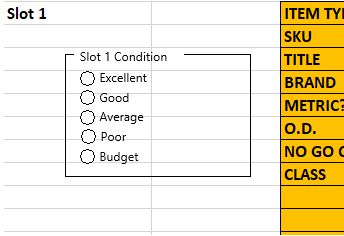
Every slot has a condition box as shown in the picture above. When listing thread gages, always select one of these five conditions - this will impact the pricing of the gage, and there can often be a big difference in price range from Excellent to Budget.
This is a mostly subjective decision which does not necessarily have one correct answer. The most important thing to consider is the condition of the threads. Damage to a plug gage handle or the face of a ring gage should also be taken in to consideration, but are not quite as important in determining the overall condition. Contact your trainer for guidance if you are not sure about the condition of a thread gage.
The Special Condition section at the bottom white section of the template slot should be used for any special notes about the item's condition such as damage or modification. Try to be specific when describing the condition (ex. "Minor damage to the bottom threads of the No Go member"), and reference pictures that point out the damage / modification if applicable. For the majority of thread gages, this section will be left blank.
Once all information has been entered, click here for the next steps.
