INSERT IDENTIFICATION
Most types of inserts have identification systems which relate to various aspects of the insert itself. Understanding these systems can help you to identify and describe not only inserts but the tools that use them as well.
For information on identifying insert types, please refer to the Inserts FAQ page.
Turning inserts can be specified in either ANSI (American) or ISO (metric) designations and are frequently labeled with both on their packaging. The ANSI designation consists of four letters followed by three single-digit numbers, and the ISO designation consists of four letters followed by three two-digit numbers. These letters and numbers correspond to specific characteristics of the insert which are described below.
Spaces or hyphens are sometimes included for clarity, but there is little consistency among manufacturers – CNMG432, CNMG 432, and CNMG-432, for example, are all considered equally valid.
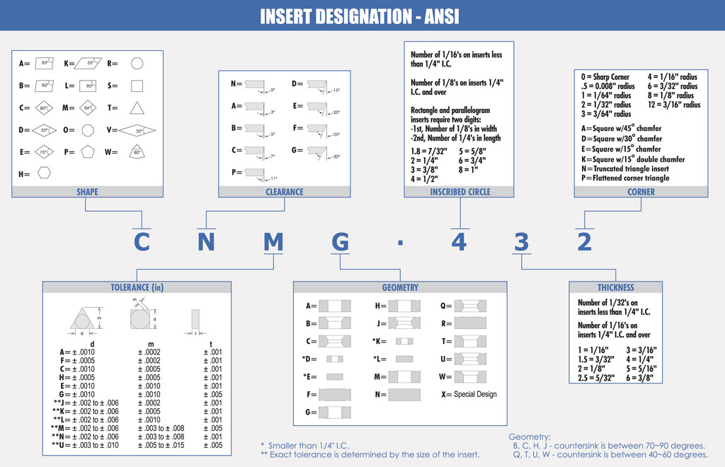
1. Shape – This can be determined easily by simply looking at the shape of the insert, although measuring the angle with a protractor may be necessary to differentiate between very similar shapes such as A and B. The most common shapes are C, D, R, S, T, V, and W.
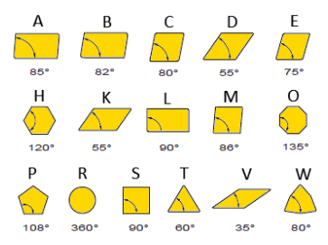
2. Clearance – This refers to the angle of the cutting edge and can be measured with a protractor.
3. Tolerance – This refers to the degree of accuracy of the insert size. Unfortunately, there is not a way for us to measure this, so if you are trying to identify an unlabeled insert you will not be able to determine this part of the label.
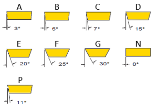
4. Geometry – This describes the insert’s hole shape and chip breaker type. Some insert holes have a countersink on one or both sides, while some inserts do not have holes at all.
A chip breaker is a feature of some inserts that breaks up the chips that are removed from the material that is being cut, so that they are removed in small pieces rather than long strands. An insert may have a chip breaker on one, both, or neither side. Chip breakers can have many different appearances, all of which should be easily distinguishable from the flat, smooth face of a non-chip breaker insert.
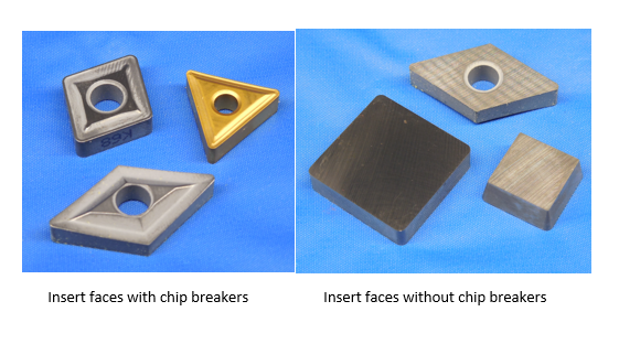
5. Inscribed Circle (I.C.) – This measures the diameter of an inner circle that touches all sides of the insert. This illustration more clearly shows what that means:

For most insert shapes, this can be easily determined by using calipers to measure the distance from one side of the insert to the opposite side. Triangle inserts, however, are a little more complicated – the I.C. can be determined by measuring the height (“H” in the illustration above) and multiplying that number by 2/3. So, for example, a triangle with a height of 3/8” has an I.C. of ¼” (.375 x 2/3 = .25)
-For inserts with an I.C. that is less than ¼”, this number corresponds to the number of 1/16ths of the I.C. (1/16” = 1, 1/8” = 2, 3/16” = 3…)
-For inserts with an I.C. that is ¼” or greater, this number corresponds to the number of 1/8ths of the I.C. (1/8” = 1, ¼” = 2, 3/8” = 3…)
-Rectangle and parallelogram inserts (shapes A, B, K, and L, specifically) require two digits: The number of 1/8ths in width, and then the number of 1/4ths in length. (ex. 3/8” width x 1/2” length = 32)
6. Thickness – This is simply the thickness of the insert, which can be easily measured with calipers.
-For inserts with an I.C. that is less than ¼”, this number corresponds to the number of 1/32nds of the insert thickness (1/32” = 1, 1/16” = 2, 3/32” = 3…)
-For inserts with an I.C. that is ¼” or greater, this number corresponds to the number of 1/16ths of the insert thickness (1/16” = 1, 1/8” = 2, 3/16” = 3…)
7. Corner Radius – This refers to the degree to which the corner is rounded and can be measured using a radius gage. The number corresponds to the number of 1/64ths of the radius (1/64” = 1, 1/32” = 2, 3/64” = 3…)
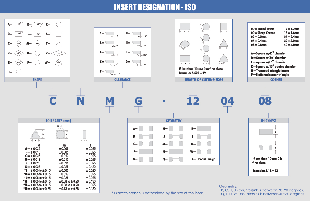
For the ISO designation, the four letters (Shape, Clearance, Tolerance, and Geometry) are all the same as ANSI. The three numbers, however, are slightly different:
5. Length of Cutting Edge – The chart above demonstrates the cutting edge for each shape. This is measured in millimeters, rounded down. If the length is less than 10mm, put a 0 in front (ex. 9.525mm = 09)
6. Thickness – This is the same as in the ANSI designation, except that in this case it is simply the measurement in millimeters, rounded down. As with the cutting edge length, put a 0 in front if the thickness is less than 10mm.
7. Corner Radius – This is the same as in the ANSI designation, except that in this case the number corresponds to the number of 1/10’s of a millimeter (.2mm = 02, .4mm = 04, 1.2mm = 12…)
Listing Turning Inserts for Indexable Tooling
When it comes to tools that use turning inserts such as boring bars and turning tool holders, the full four-letter-three-number identification is typically not required to describe the type of inserts held by the tool. Instead, only the first two letters and first two numbers are strictly necessary (for example, “CN-43” or “SH..11 04” ). This is because these tools can use a variety of different inserts, so long as the shape, clearance, inscribed circle, and thickness match. As with the full identification, you will likely encounter different versions of these abbreviations using spaces, hyphens, or ellipses, and there is not one single correct way to notate them.
Milling inserts have similar ANSI and ISO designations to turning inserts – they begin with four letters and two numbers which correspond to the same characteristics as their turning counterparts, however this will be followed by several more letters and numbers which describe aspects such as cutting edge form, hand direction, and rake face angle. Many of these milling-specific characteristics will not be easily identifiable if they are not labeled, but understanding what they refer to can still be useful. For a full breakdown of milling insert nomenclature, refer to this link: https://www1.mscdirect.com/images/solutions/kenna...
Listing Milling Inserts for Indexable Tooling
Like with turning inserts, typically only the first two letters and first two numbers are necessary for describing the milling inserts held by a tool such as a face mill or indexable end mill. However, with milling inserts it is more common for a manufacturer to list inserts more specifically (often with all four letters such as “APKT1105..”) and so whenever this information is available it is preferred to match the manufacturer’s specifications.
“TOP NOTCH”-STYLE THREADING AND GROOVING INSERTS
The Kennametal “Top Notch” style is one of the more popular types of threading and grooving inserts. Identification systems for these styles are described in the charts below. As with milling inserts, some of the characteristics described may not be easily identifiable when unlabeled.
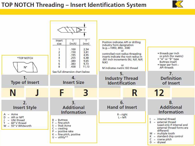
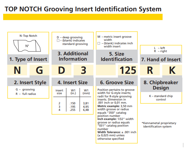
Listing Top Notch Inserts for Indexable Tooling
Boring bars and other tools that use Top Notch-style inserts typically only list the type (1), size (4), and hand (6) – so the examples used in the charts above would both be “N3R” or “N-3-R” (again, the exact way the abbreviation is spelled out can vary). As with the other insert types, this is because these tools will be able to hold any insert that matches those particular specifications.
LAYDOWN TRIANGLE THREADING INSERTS
This is the other common type of threading insert, which appears somewhat similar in appearance to triangle turning inserts. The identification system is explained in the chart below.
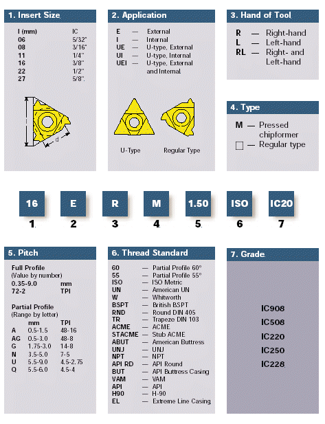
Unfortunately, most of these specifications will not be easily identified without labeling. If you need to describe laydown inserts held by an indexable tool, the best option is to list the inscribed circle and thickness of the insert, as this will at least provide the necessary size information that a customer may need.
You may encounter other types of inserts that do not fit into the categories listed above, such as spade drill inserts and thread milling inserts. There are also manufacturers such as Sandvik and Komet which often do not use the common identification systems. If you need to describe an insert that does not seem to fit into any of the standard naming systems, the best option is to provide as much information as possible about the dimensions of the insert, such as the shape, inscribed circle, thickness, the angle of the cutting edge, and any other information that may be relevant to the insert’s use.
