Always inspect for damage before and during cleaning. One of the main things to look for is damage to the flange. If there is any damage to the flange, such as in the examples below, contact your trainer before proceeding as the item should not be listed in most cases:
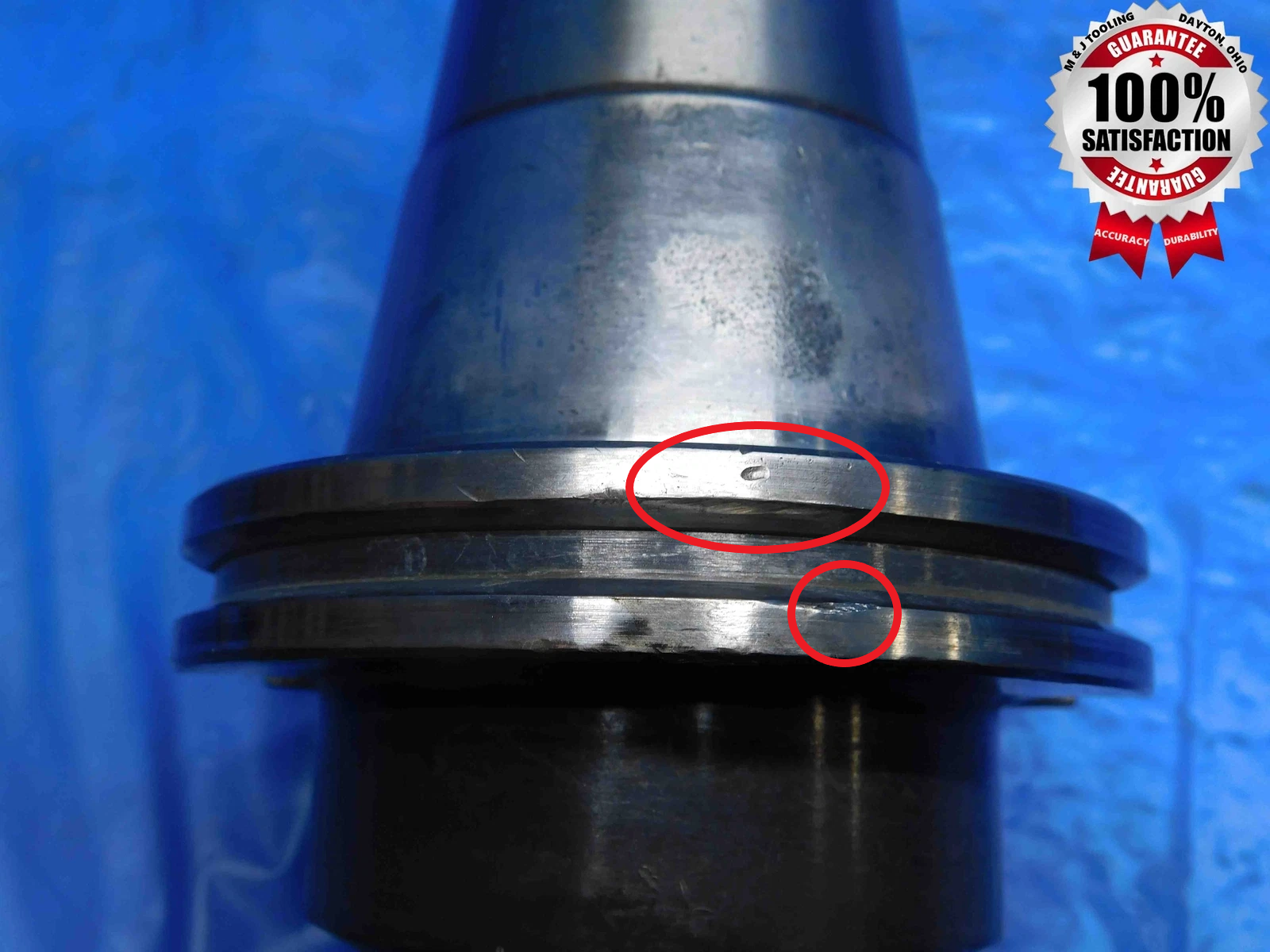
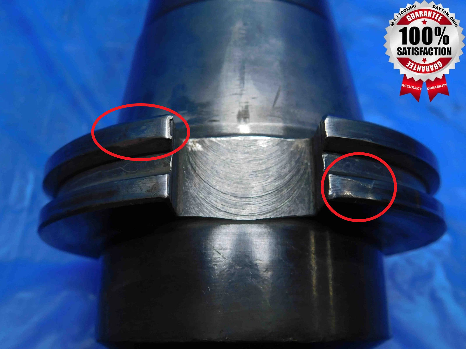
Some tool holders can be cleaned with WD-40 and Scotch-Brite like other tools, but very often tool holders will be especially rusted / covered in residue and require the use of a wire wheel, drill, or other tools. Your trainer will instruct you how to use these tools correctly and safely.
Regardless of how the tool holder is cleaned, take care not to damage or remove any labeling. Many tool holders also have black paint / coloring on their working ends which can be rubbed off if you are not careful.
Once the tool holder is clean, wipe it down with a dry rag to remove any excess residue before taking pictures.
Click here for info about how to upload pictures
While there are many different types of tool holders with various important features, the majority of tool holders will be pictured according to the following guidelines:
Note: "Working End" refers to the part of the tool holder that holds the tool, NOT the tapered side.
1st Picture: A three-quarters (or "3D") shot of the tool holder, with the working end facing the camera. If it is an NMTB Flash Change holder (refer to the NMTB section for more info), the Flash Change groove MUST be visible in this picture. If it is a Solid End Mill holder (refer to the Tool Holding Type section for more info), the set screw(s) MUST be visible in this picture.
If both Flash Change and solid end mill, and the FC groove and set screw cannot be shown in the same picture - Prioritize the groove, BUT make sure the set screws are clearly shown in the next picture
2nd Picture: A side view of the tool holder, with a tape measure at the bottom of the frame to provide size reference.
3rd Picture: A close-up, head-on shot of the working end. For tool holders with nuts or end screws (specifically collet chucks, face mill holders, and stub arbors), these should be removed for this picture (if they loosen easily), but still included in the shot. Refer to the second set of pictures below for an example.
4th Picture: A close-up shot of the labeling. Depending on where the labeling is located, this may require more than one picture. If there is no labeling, or if it is too faded to be readable in a picture, skip this picture.
5th Picture: If the tool holder is Coolant Thru (see the Coolant Thru section at the bottom of this page), take a close-up shot of at least one of the coolant holes / channels, since they will often not be immediately noticeable in the other pictures. If the coolant holes are located on the working end, or somewhere else that is clearly visible in other pictures, this extra picture is not necessary. Refer to "Picture 5" in the first example below.
Additional Pictures: Any damage to the tool holder, particularly to the working end or taper, must be clearly pictured. Use a pen to point to the damaged area.
Additional pictures may also be necessary for special types of tool holders with features that are not properly captured in the previous pictures. This can be especially true for integral tool holders, or when there is tooling in the holder. If you are not sure whether a certain aspect of a tool holder needs to be specifically pictured, ask your trainer to confirm if it is necessary.
IMPORTANT: Not all held tooling should be clearly shown in pictures. In particular, non-indexable cutting tools such as drills and end mills should not be advertised in the listing unless specified by your trainer. It is very possible for these types of tools to be damaged during storage or shipping, and so we do not want customers to think they are getting a usable, working tool when we cannot necessarily guarantee it will still be in that condition when they receive it. In these cases, have as little of the tool showing in the pictures as possible while still capturing all of the important aspects of the tool holder. Refer to the 3rd set of example pictures below for a demonstration of what this will look like, and ask your trainer if you have any questions about picturing tooling in tool holders. Note: this does not apply to integral tooling, which should always be pictured in detail.
Refer to the examples below:
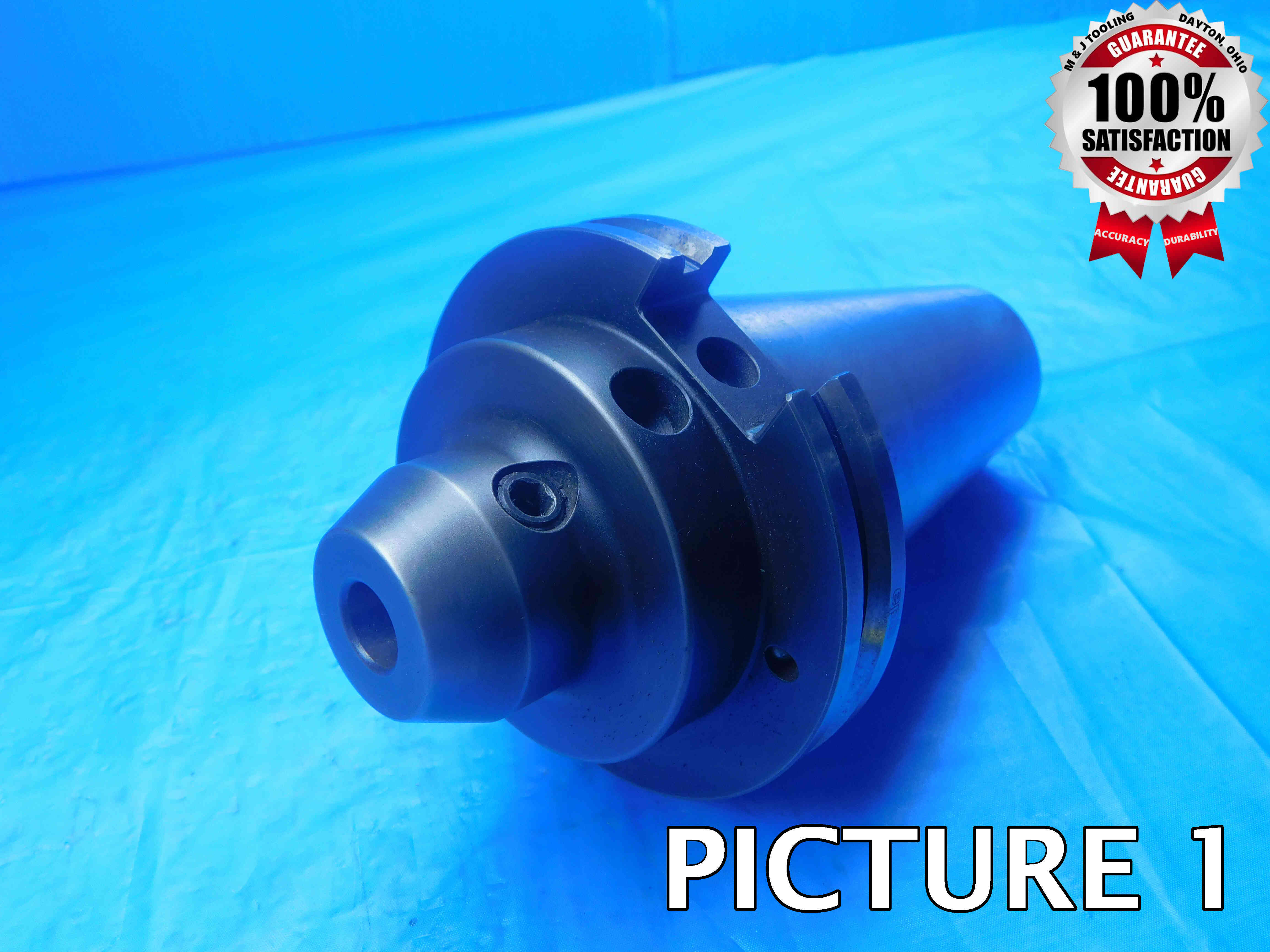
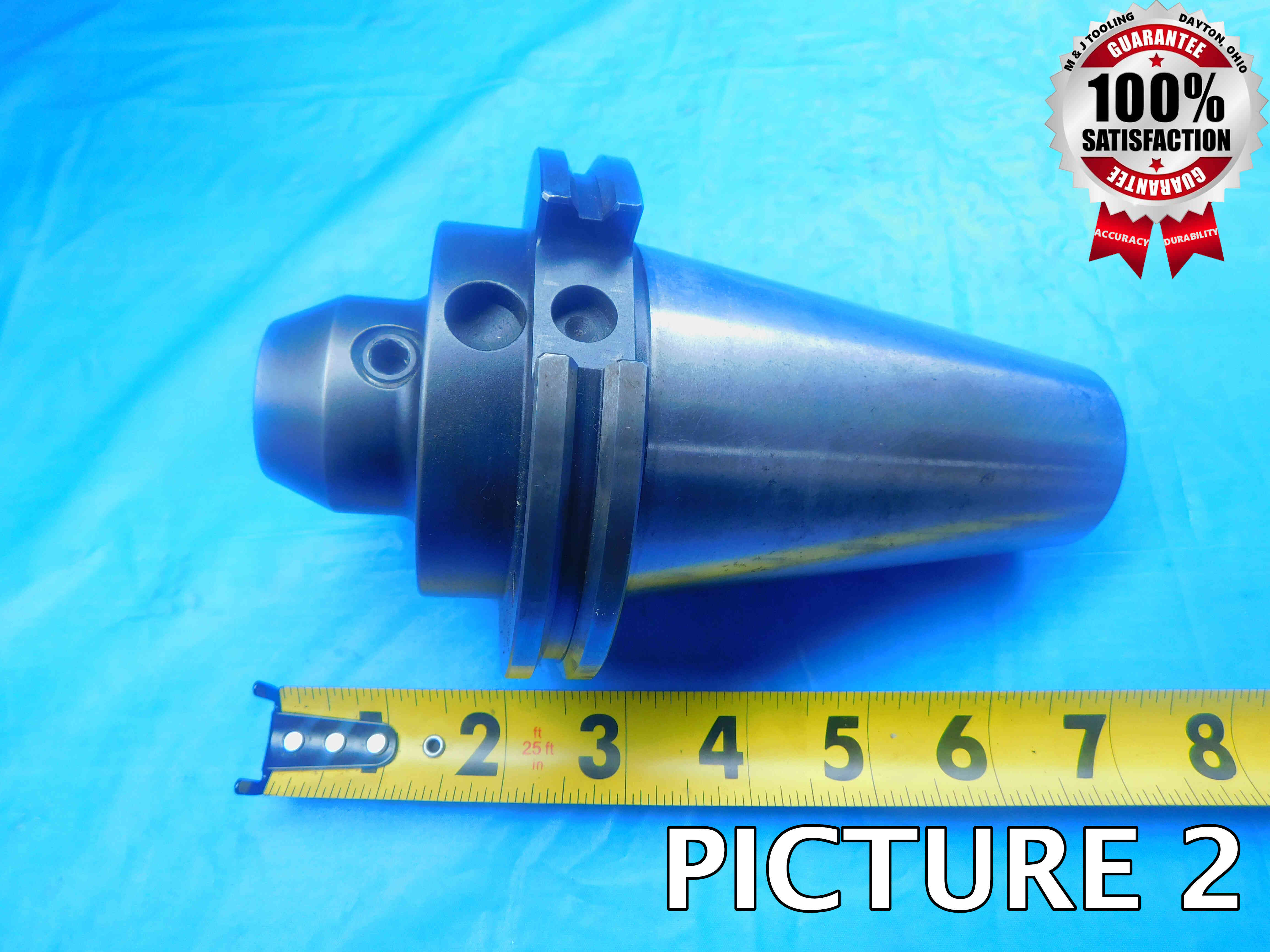
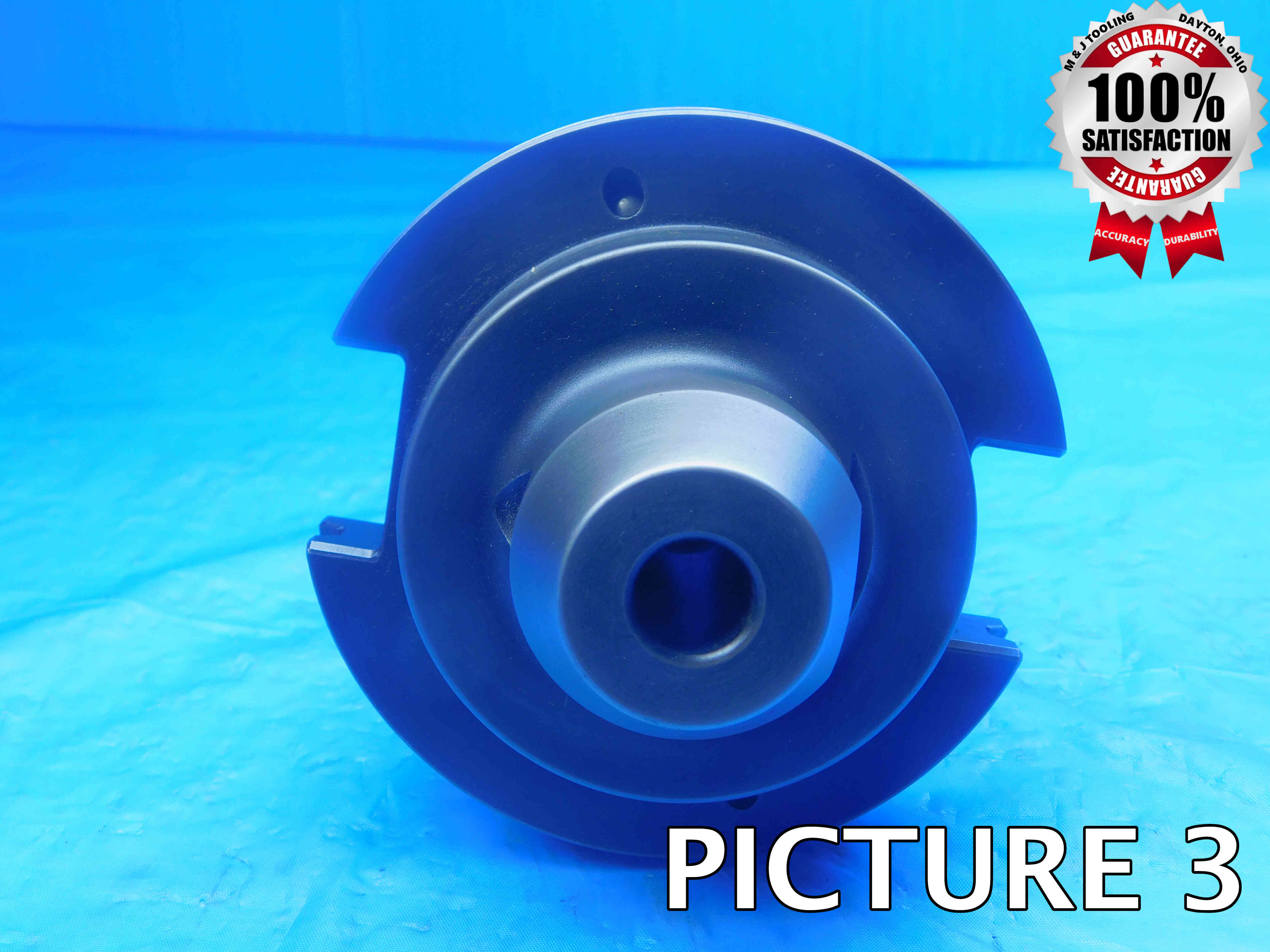
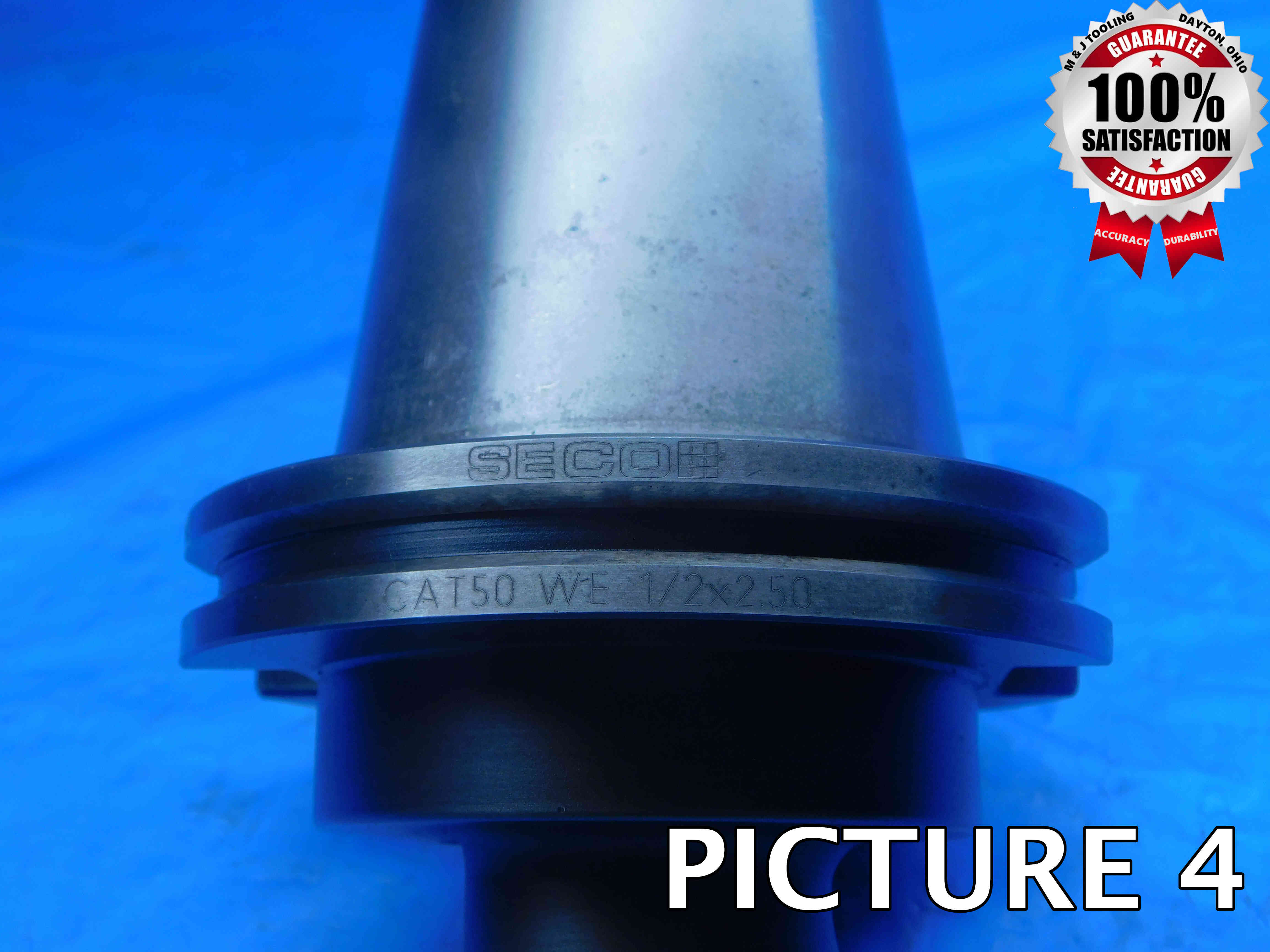
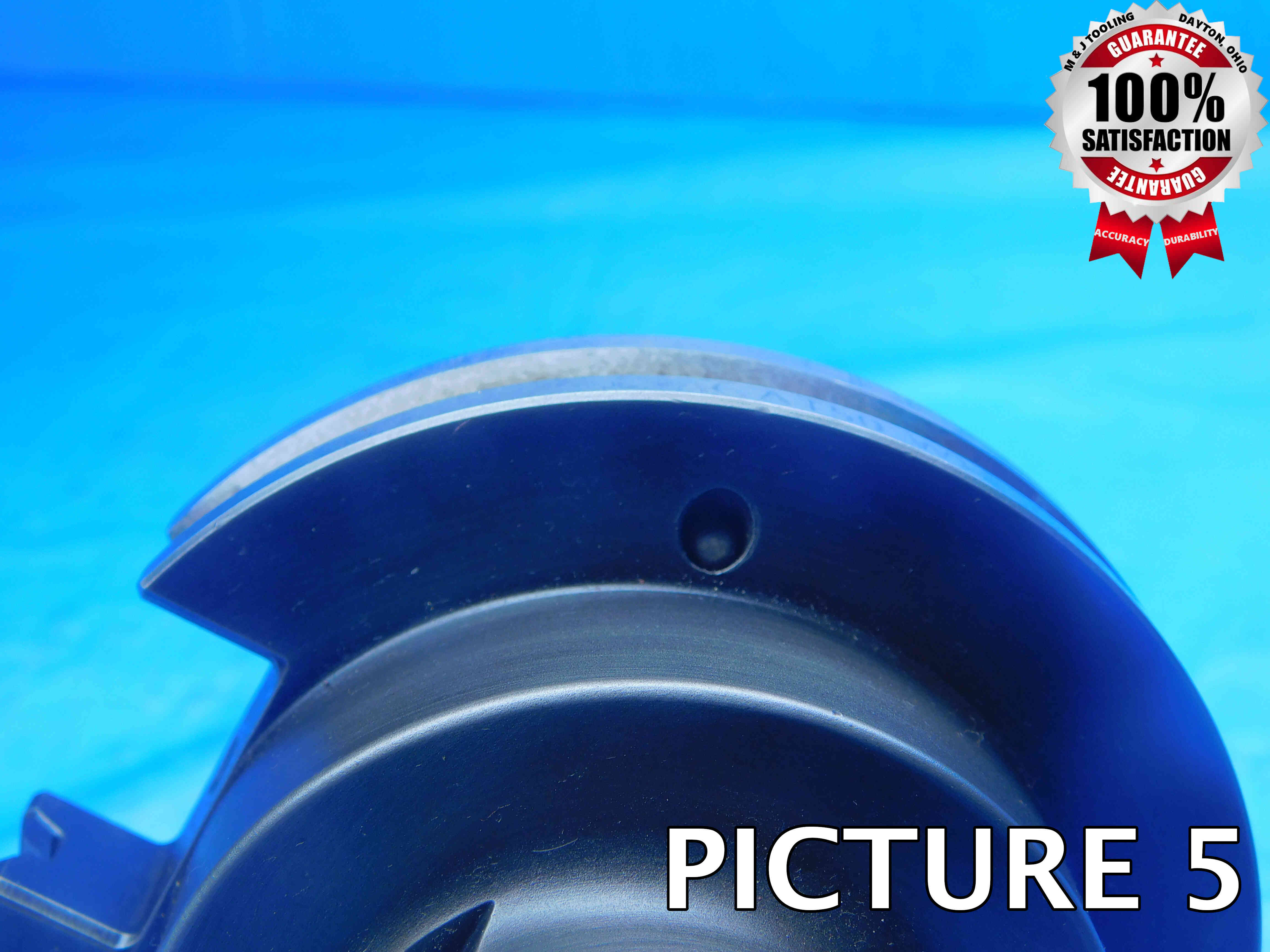
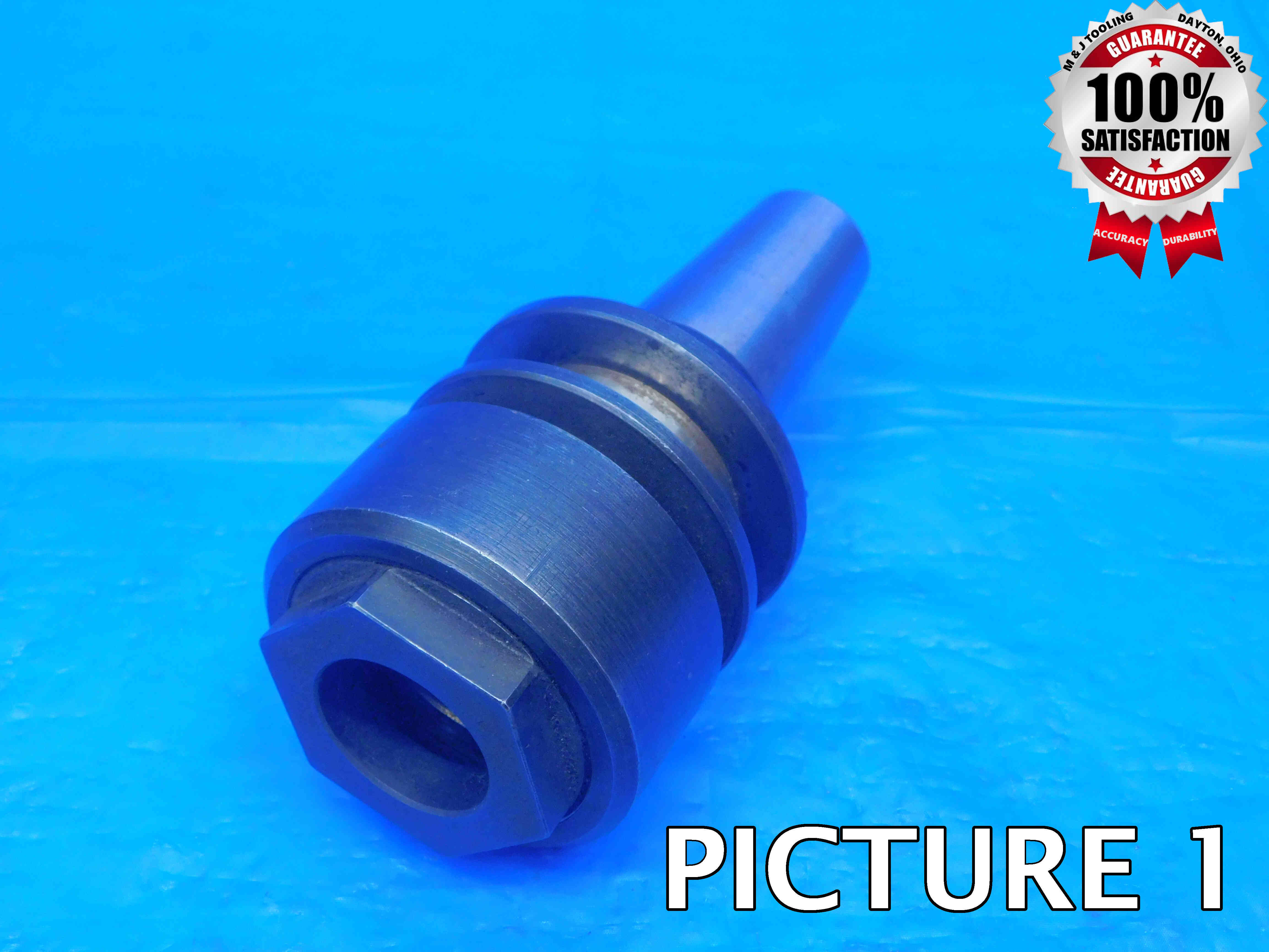
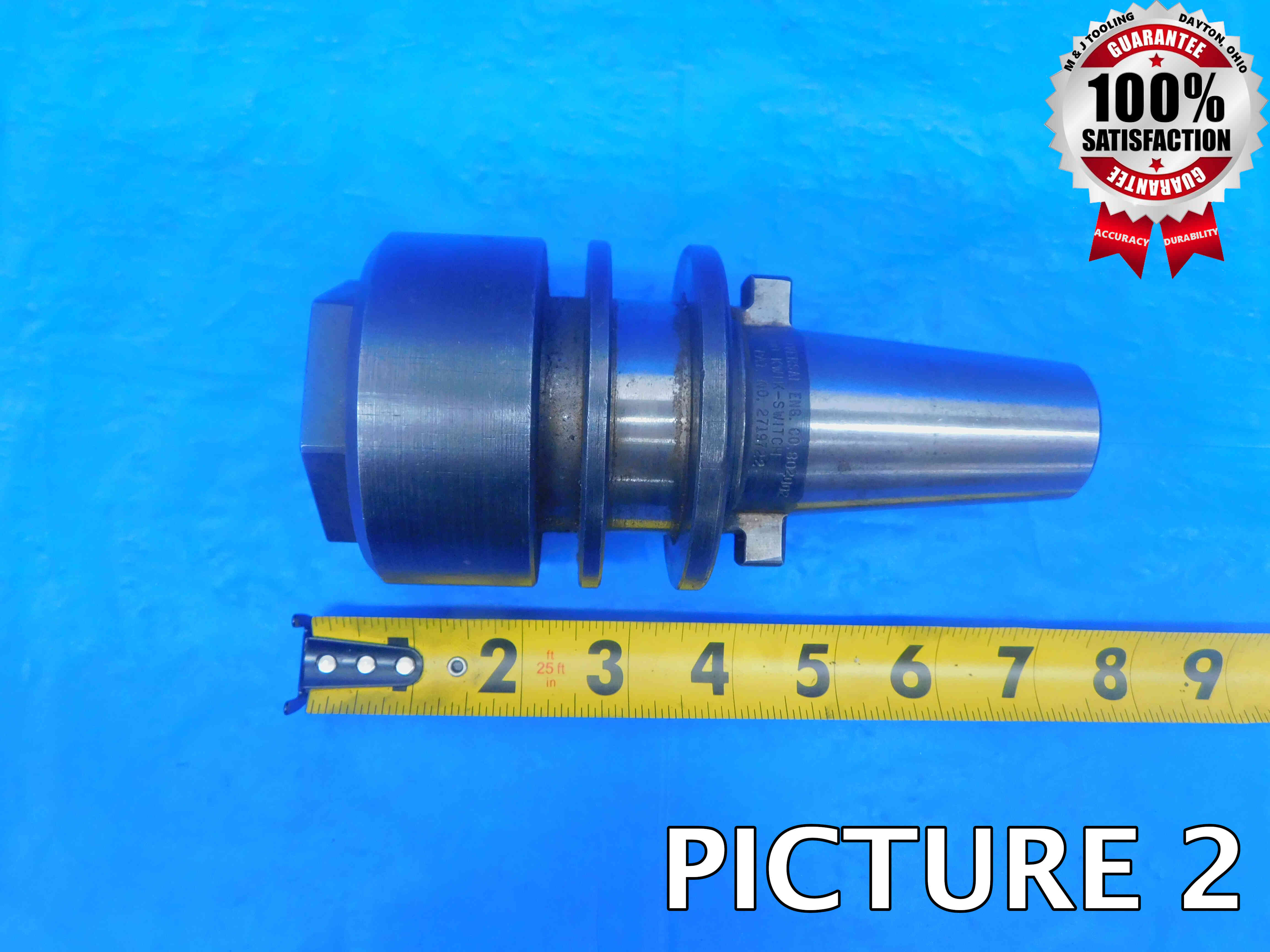
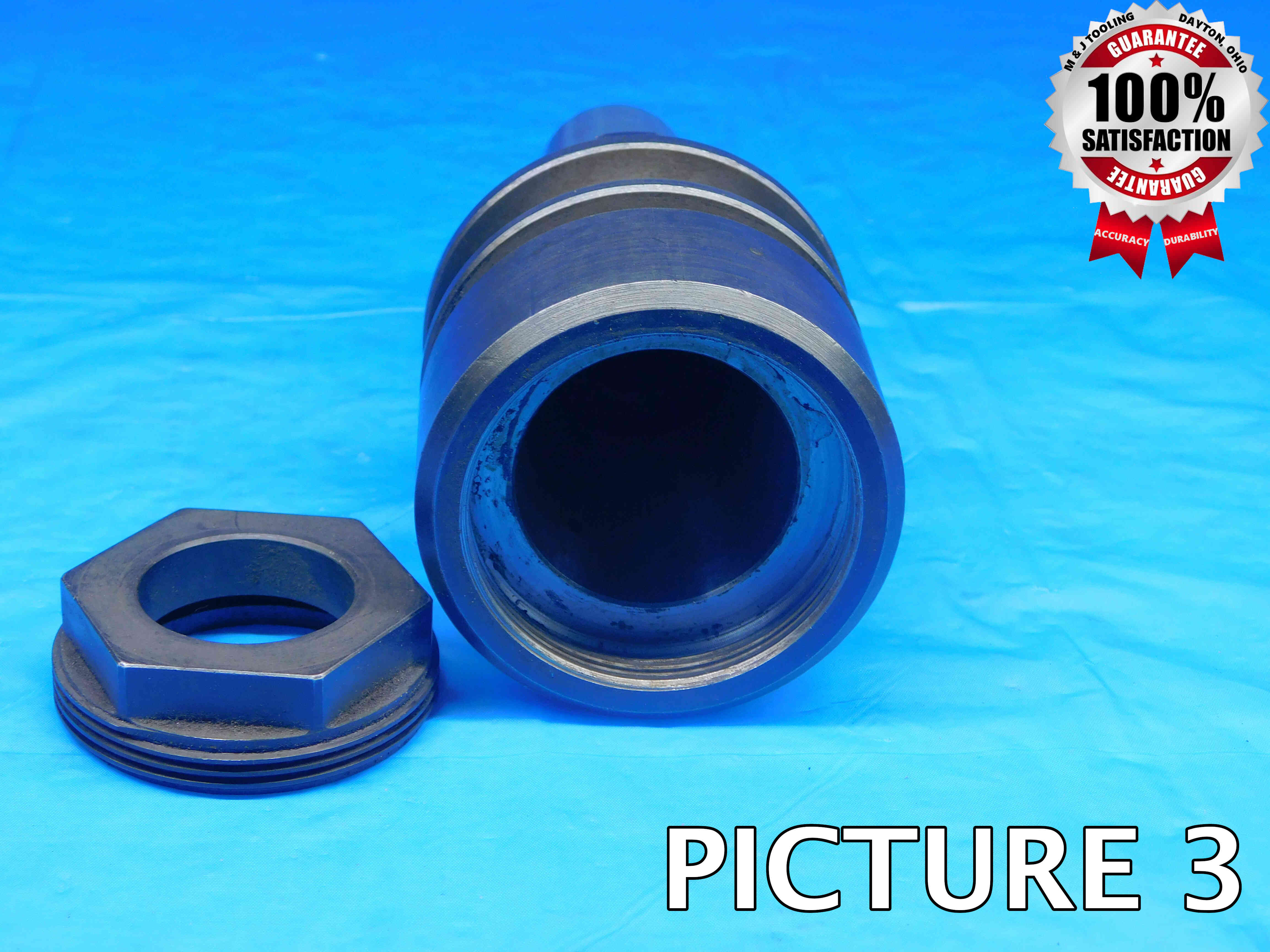
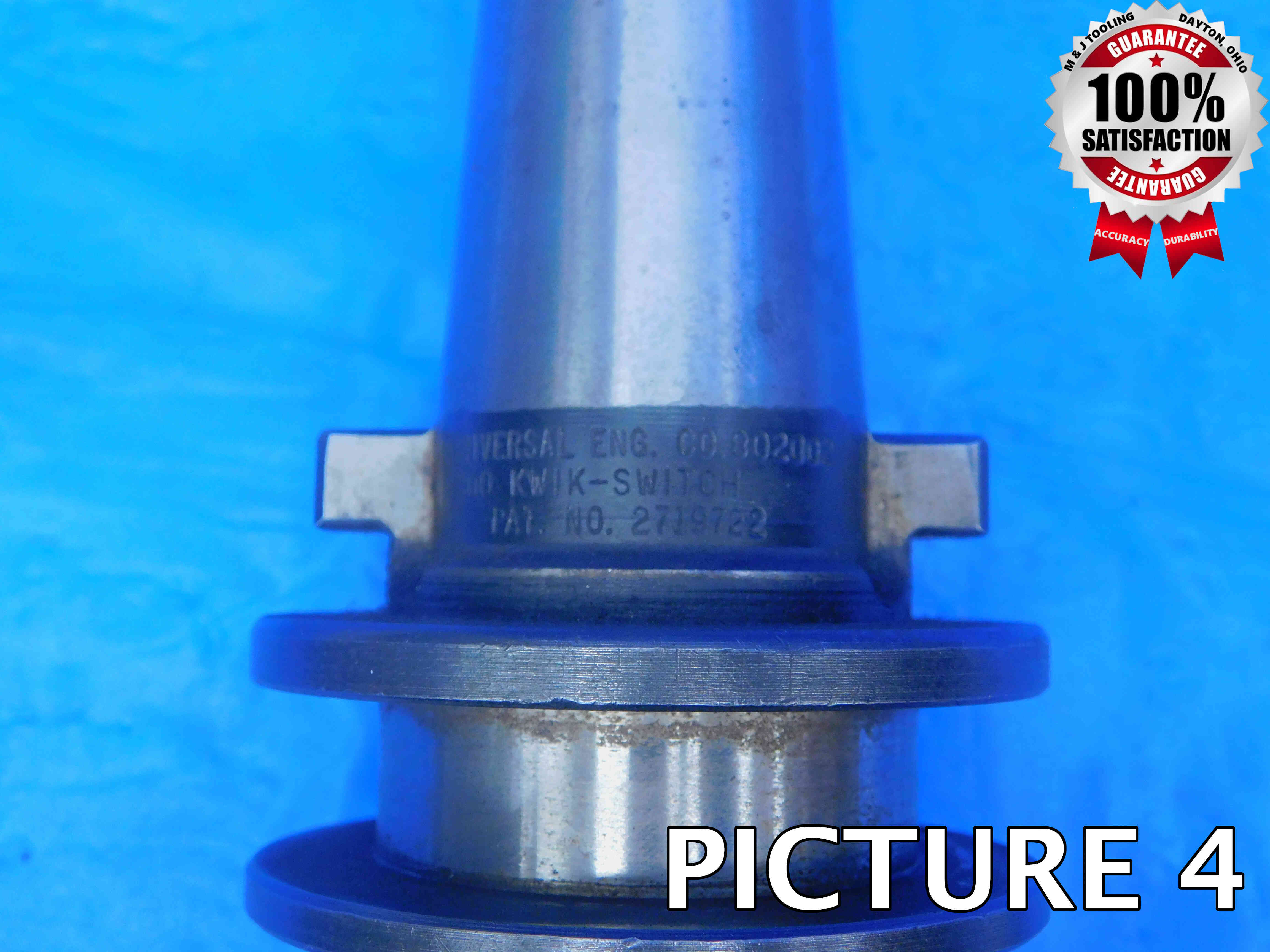
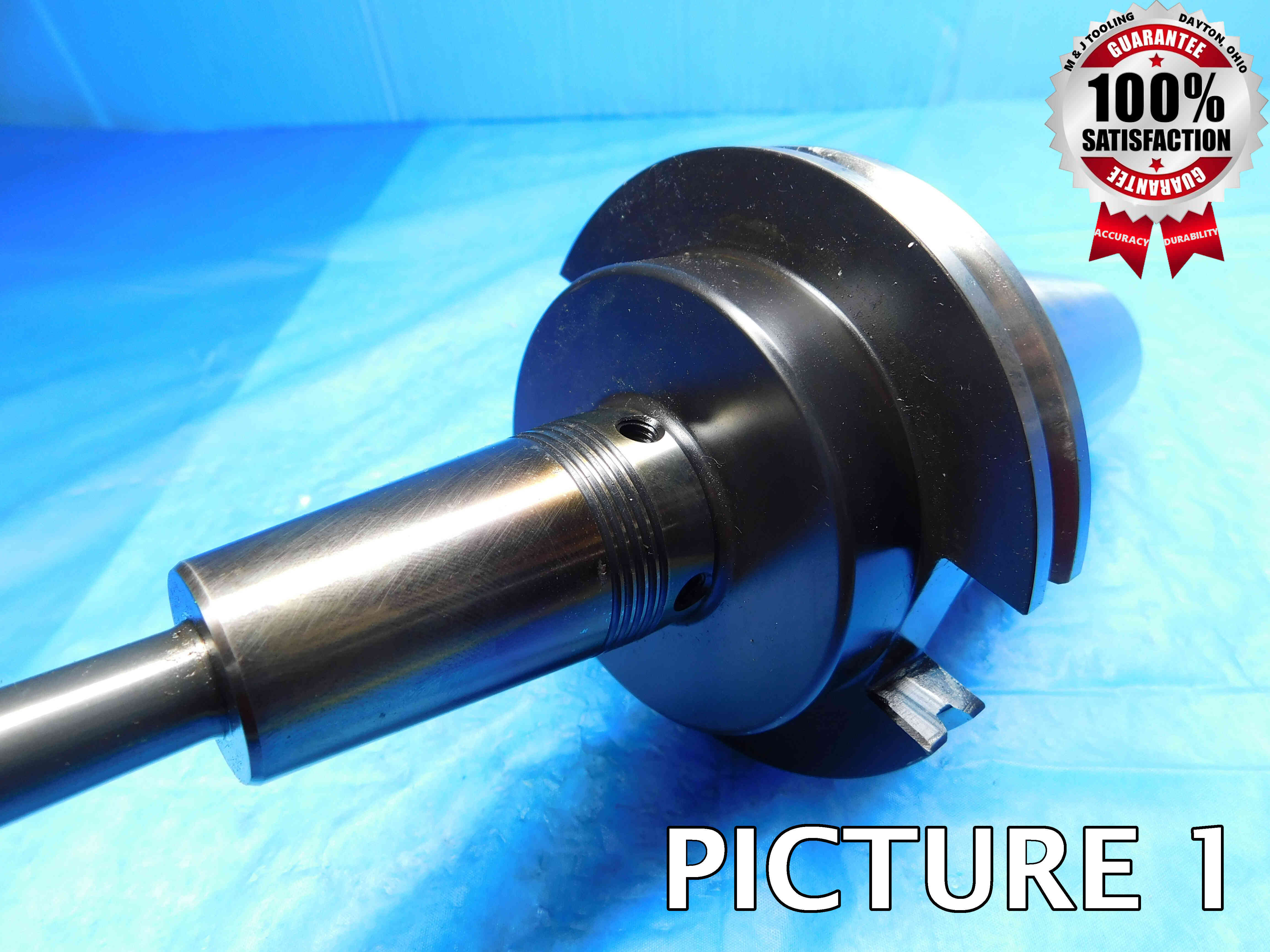
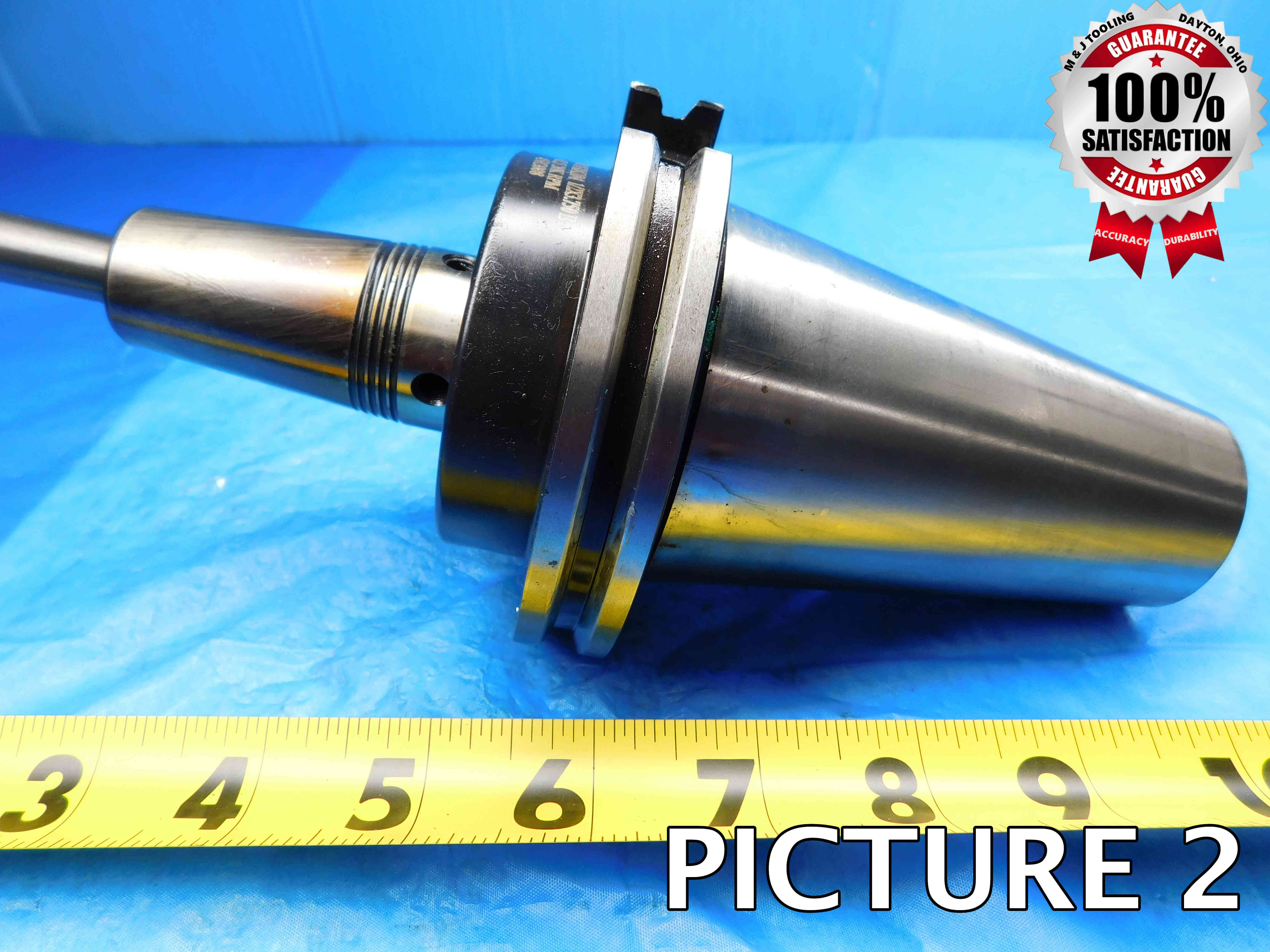
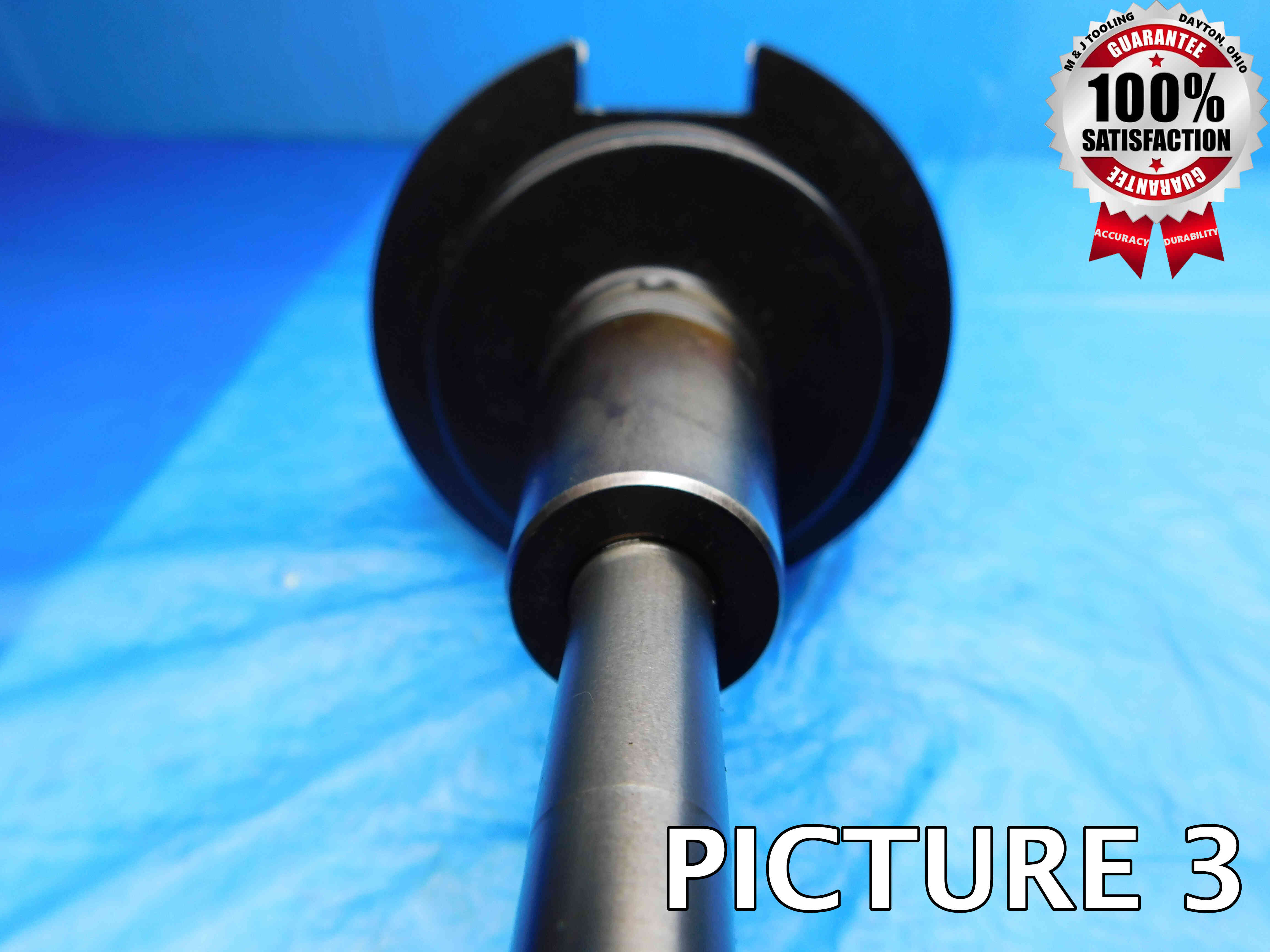
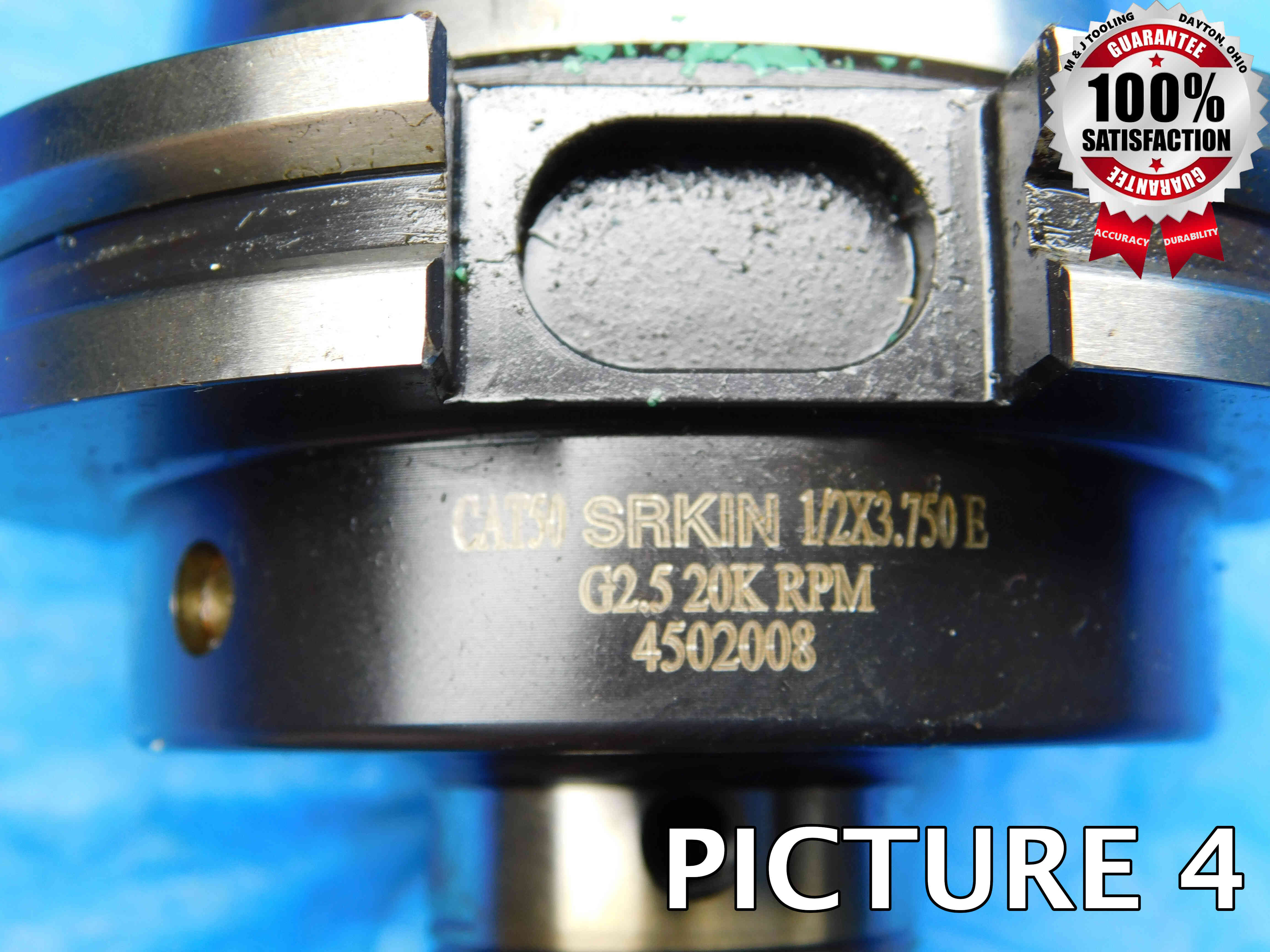
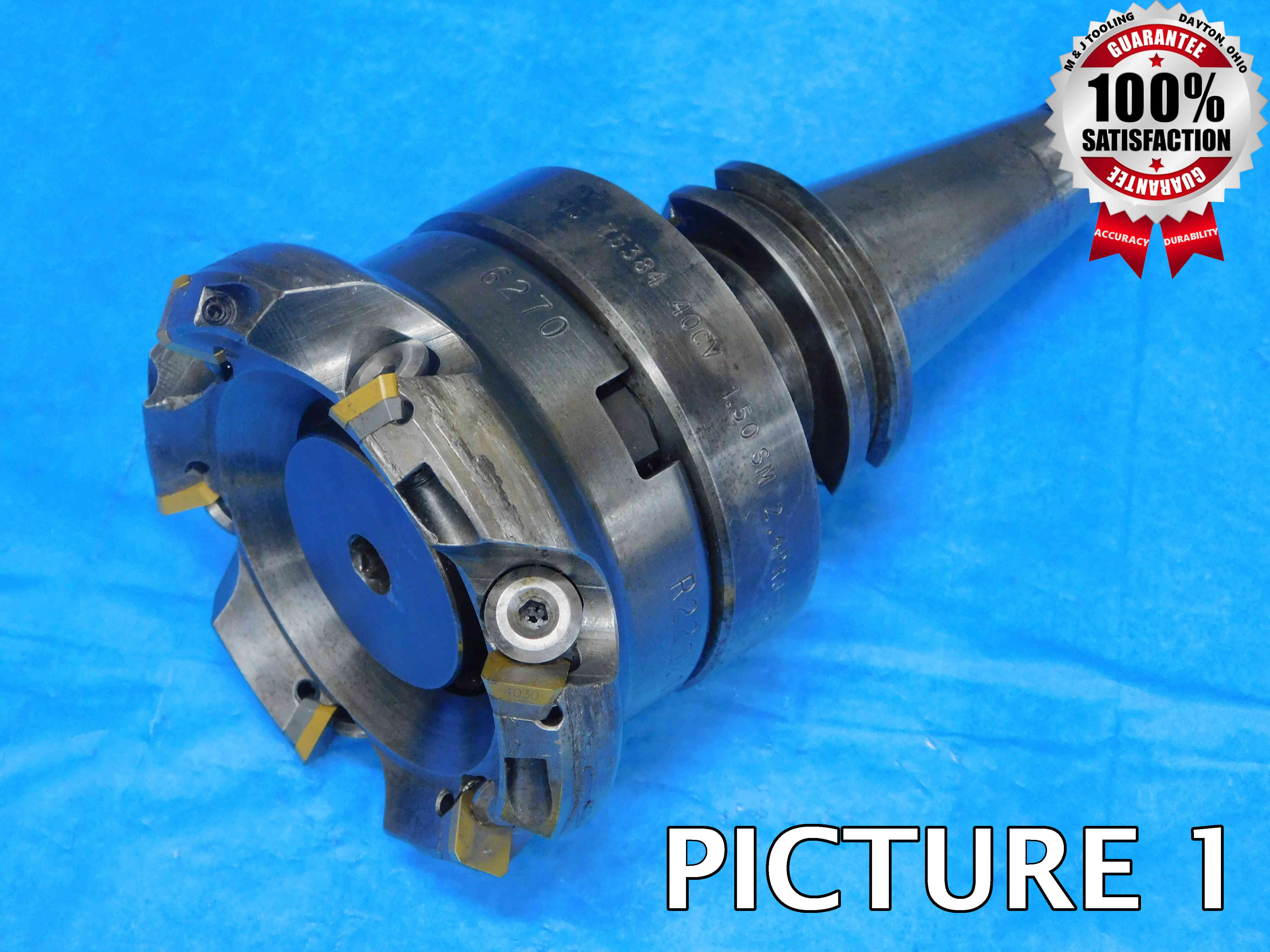
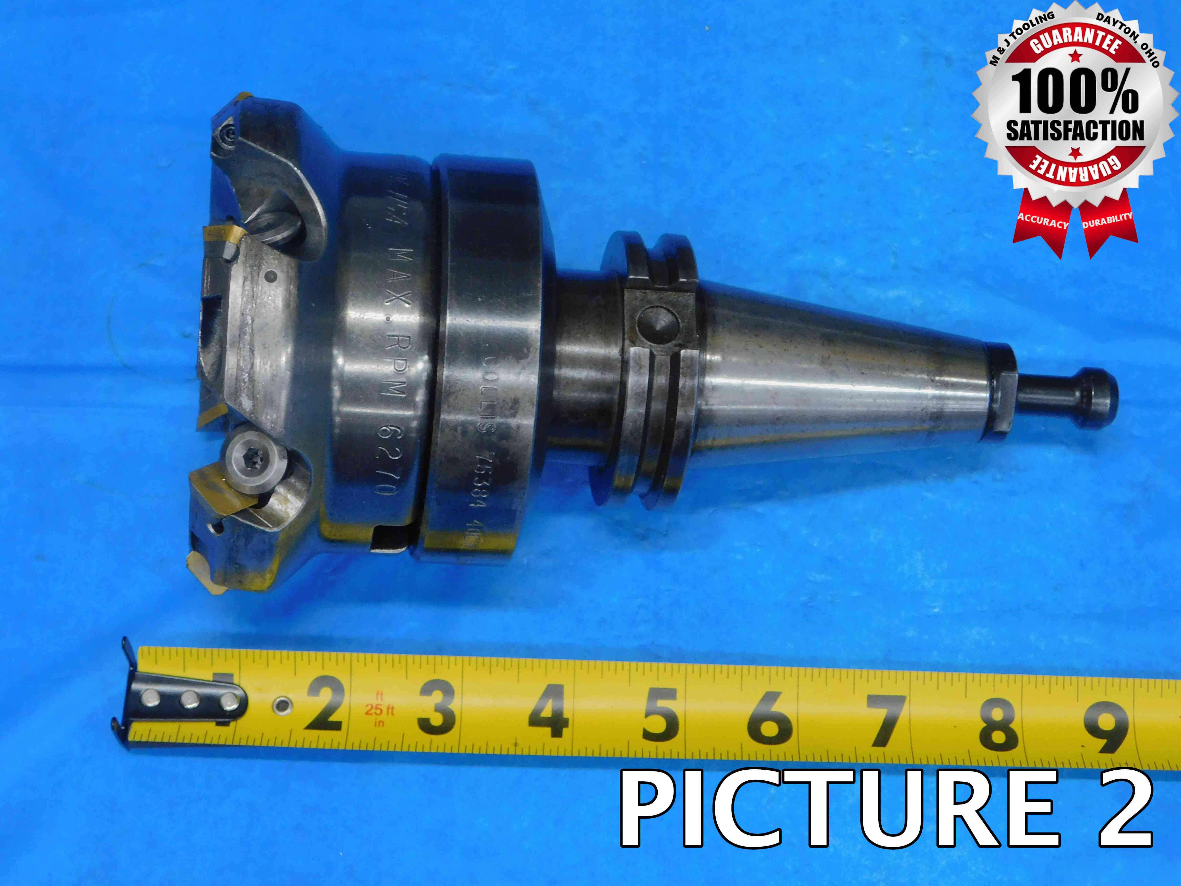
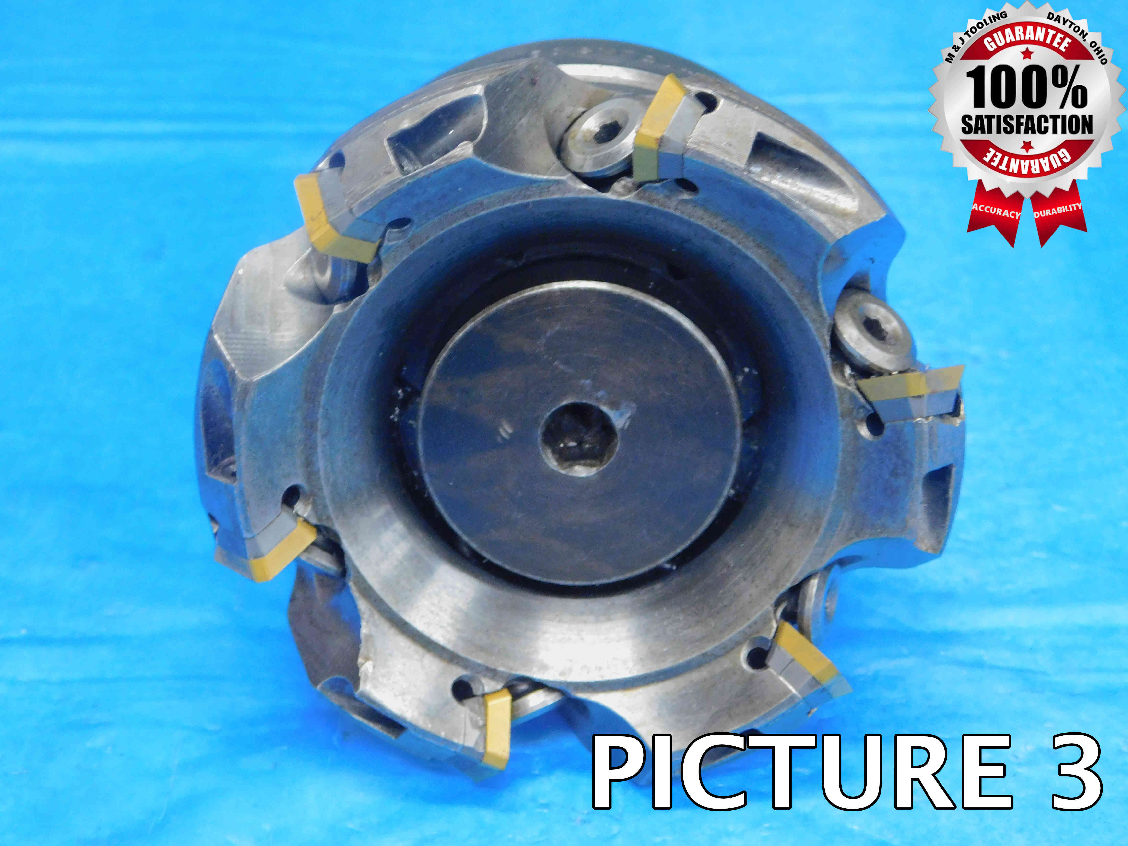
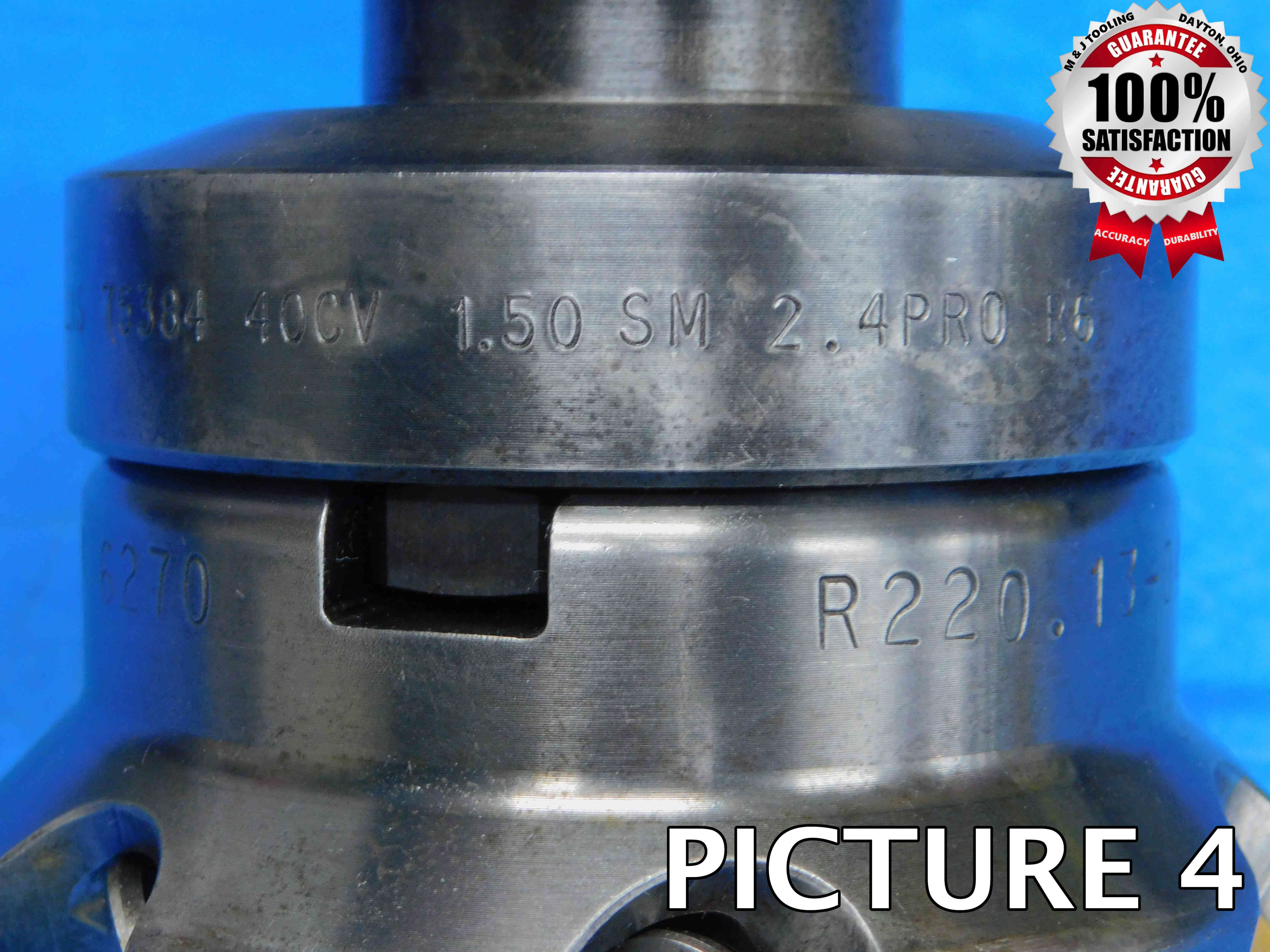
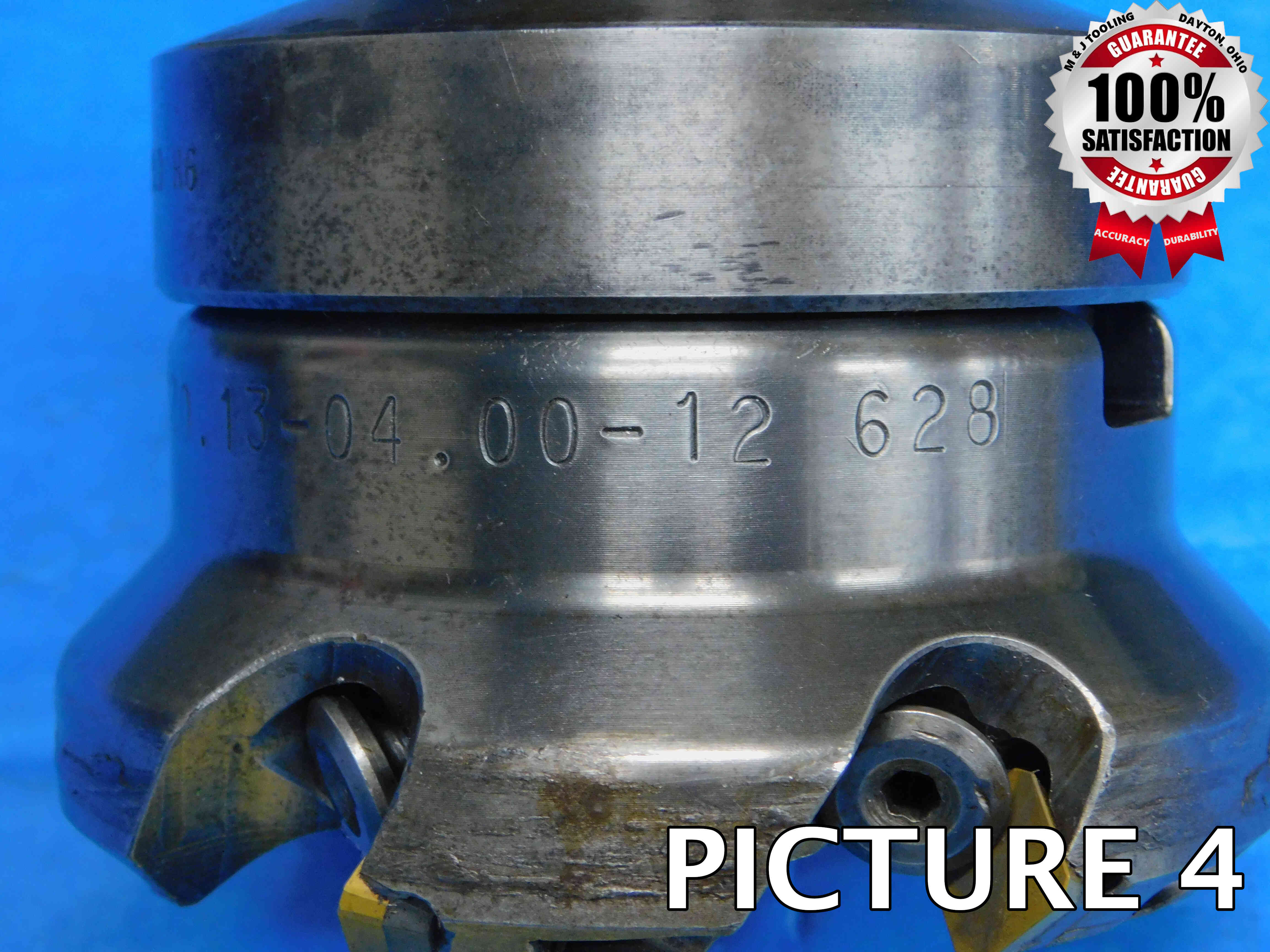
Watermarking Tool Holder Pictures
You have probably noticed that the example pictures shown above are watermarked with a "Satisfaction Guarantee" badge. Be sure to select the Tool Holder watermark option when running your pictures through the Batch Image Tool.
A note about "Balanceable" tool holders:
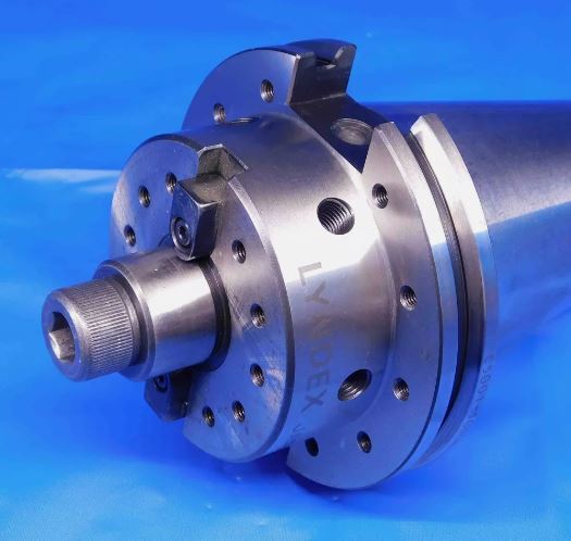
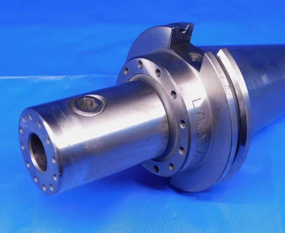
Some tool holders will contain multiple threaded holes such as the ones shown above. Screws can be inserted into these holes in order to adjust the weight balance of the tool, which can be necessary when running a machine at very high speeds in order to compensate for imperfections in the tool's symmetry which could otherwise cause the tool not to stay straight as it spins.
*Note that this is different from coolant thru holes, which are explained in more detail here*
"Balanceable" should not be considered to be a tool holding type (as it can be a feature of many different types, such as the face mill and solid end mill holders above), but instead should be included in the "Filler" section.
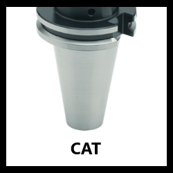
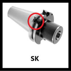
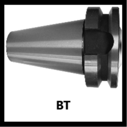
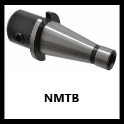
Tool holders will have both a style and size, which should be entered together with no spaces (ex: CAT50, BT45, HSK63A - Kwik-Switch is the single exception and should have a space before the size). The various styles are described in the sections below along with charts for determining the taper size. (Click an icon below to jump to that section)
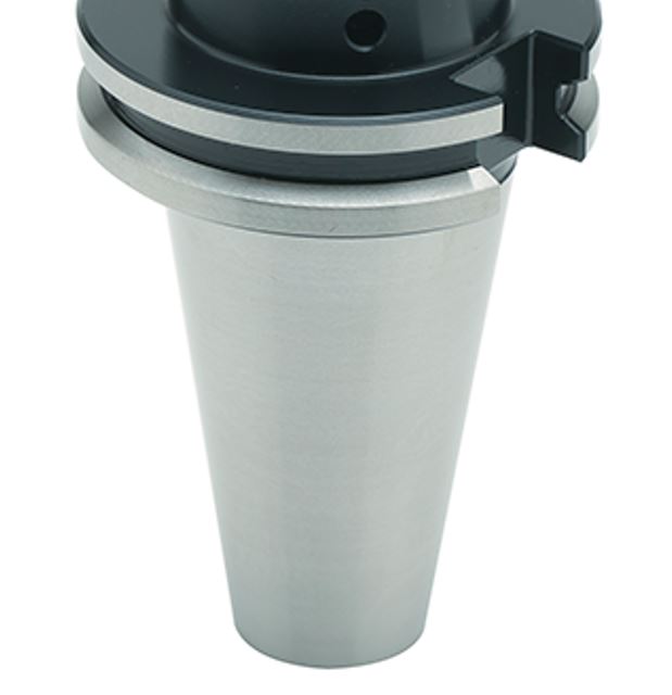
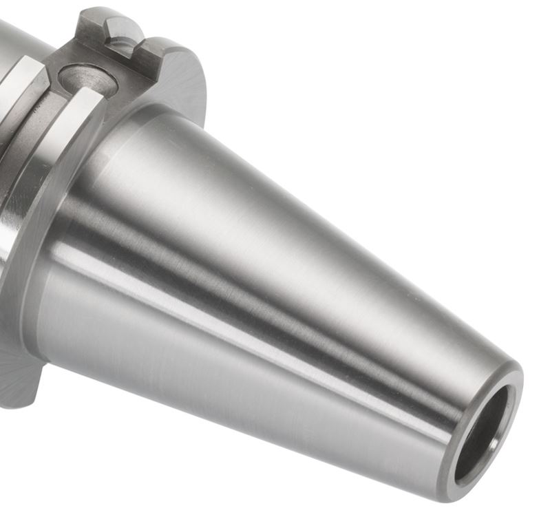
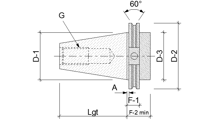
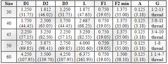
CAT Tool Holders have a slot that goes through both sections on the flange. This flange design is the main difference between CAT & BT Shanks. Their size is most easily determined by measuring D1 or D2 and look significantly different when compared. CAT is considered the US Standard for tapered shank tool holders.
Note: Dual Contact CAT
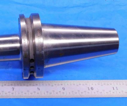
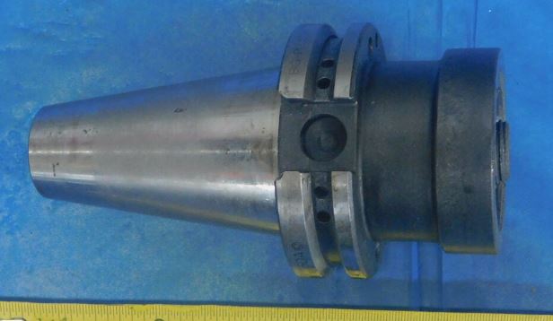
You may occasionally see CAT tool holders like the ones pictured above, in which the two sections of the flange are different widths. These are called "Dual Contact" holders and should be described as such in the listing (ex., "Dual Contact CAT40"). These can be more desirable than standard CAT tool holders to some customers due to the wider bottom flange creating a tighter, more rigid fit with the machine spindle it connects to.
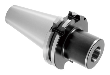
SK Tool Holders are almost identical to CAT tool holders, with the only differences being that SK tool holders use metric retention knobs and also have an extra v-shaped notch in the flange which is used for alignment in certain machines. SK tool holders have the same taper sizes as CAT and can be used in machines designed for CAT tool holders (but the reverse is not true - CAT holders cannot be used in machines designed for SK because they lack the alignment v-notch).
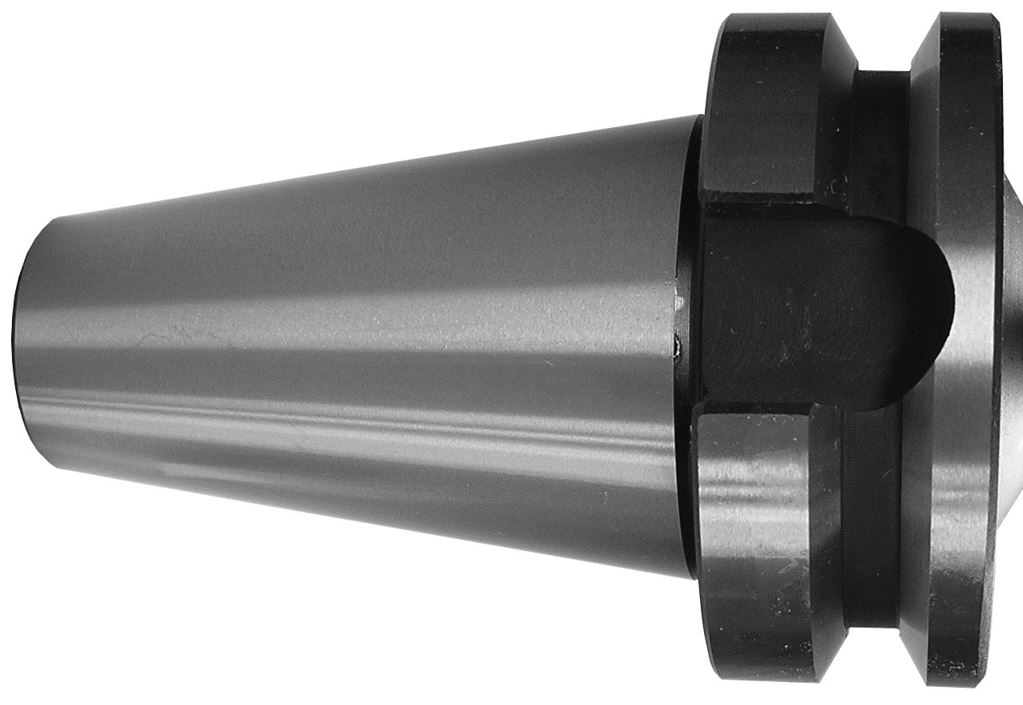
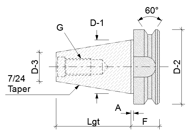
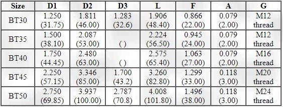
BT Tool Holders have a slot that goes through the top (usually) larger flange and partially through the bottom. This flange design is the main difference between CAT & BT Shanks. Their size is most easily determined by measuring D1 or D2 and look significantly different when compared.
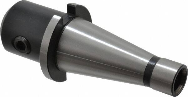
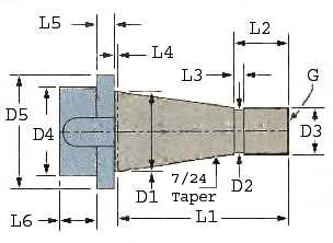

NMTB Tool Holders have only one flange and may either be large resembling BT or small resembling CAT. They do not taper all the way to the pull stud, which is the easiest way to differentiate NMTB. The easiest way to determine size is by measuring D1 or D5. NMTB may also be referred to as Quick Change Shank.
Note 1: Flash Change
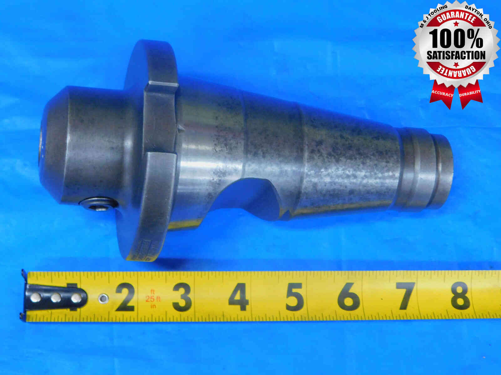
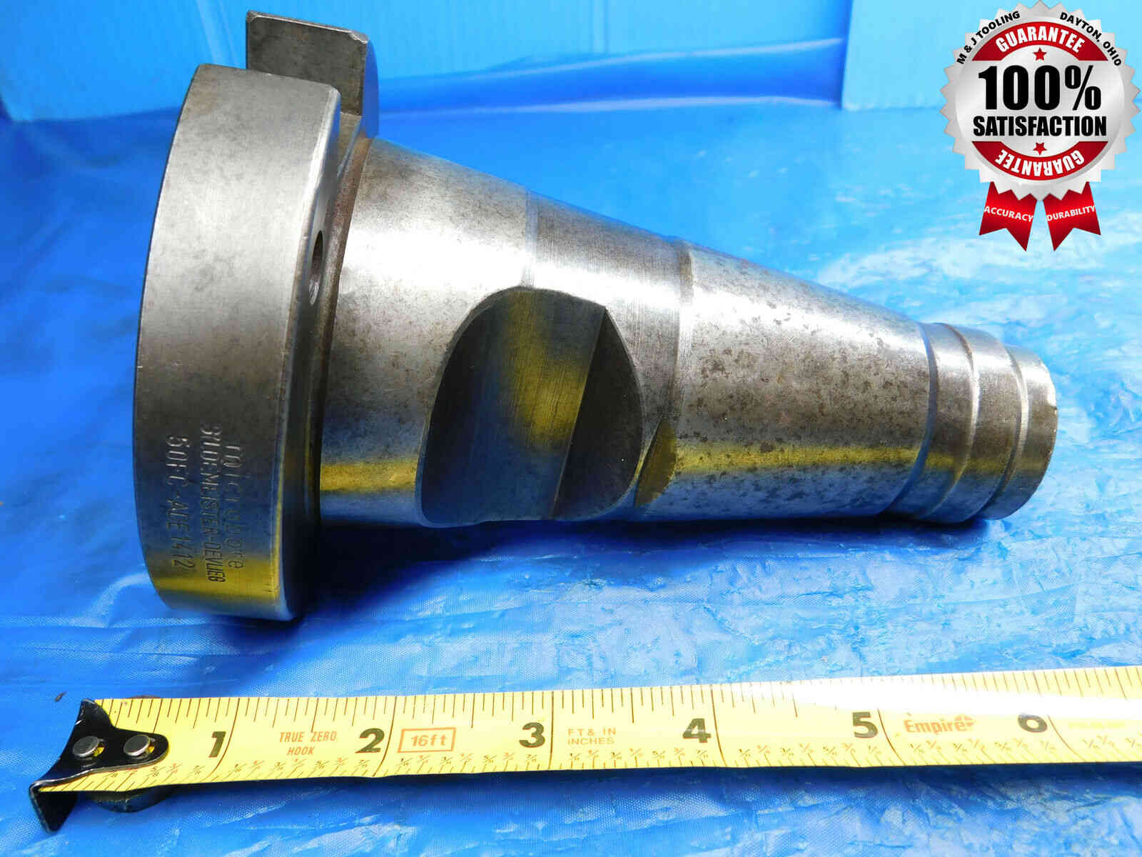
The company Devlieg (also known as Universal Engineering and TSD) produces a line of NMTB "Flash Change" holders. These look like standard NMTB holders except for a large groove in the taper that is used for locking the holder into a special Flash Change receiver. "Flash Change" should always be included in the listing title for these tool holders.
Note 2: NT Tool Holders
NT Tool Holders are almost completely identical to NMTB tool holders, with one exception - the internal threading of the nose is metric instead of imperial. These are very uncommon, and it is generally not worth our time to check every NMTB holder to make sure it's not actually an NT holder, so you can assume NMTB unless there is something in the labeling that implies it might be NT, or if other measurements (such as a solid end mill I.D. or a face mill Pilot O.D.) are metric, which could indicate that the nose thread is metric as well. Contact your trainer for assistance with checking threads if you believe you may have an NT tool holder.
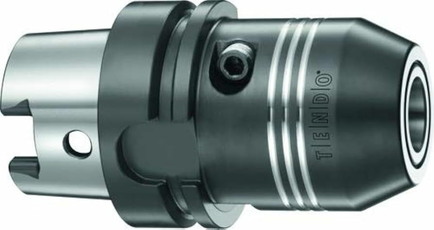
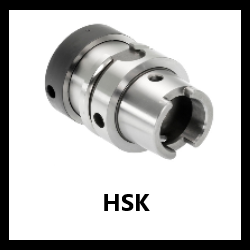
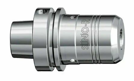
HSK Tool Holders do not much resemble the other styles, having a shorter and more open taper which often has holes and/or drive key slots going through it like in the image above. They are of German design and don't use a retention knob, but rather a dual contact method providing more rigidity.
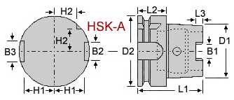
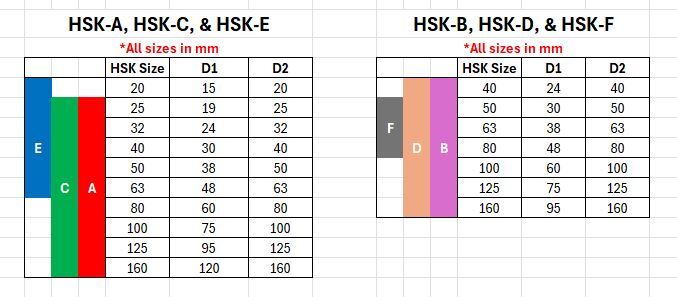
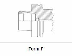
There are six different HSK forms, represented with letters from A through F, which will be described below. In addition to these forms, HSK holders come in one of ten different sizes as shown in the chart above. The size, if it is not labeled, can be determined by measuring the large end diameter of the taper and flange diameter (D1 and D2 in the diagrams above, respectively) and comparing with the charts above.
For all forms and sizes, the naming convention is: HSK[size][form]. For example: HSK63A, HSK80B, HSK100C
HSK-A

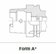
Available sizes: 25, 32, 40, 50, 63, 80, 100, 125, 160
HSK-A is by far the most common form and is the standard for most machines and applications. The taper has drive key slots which often (but not always) have holes above them like the picture above. A groove separates the flange into two sections.
HSK-B
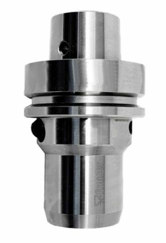
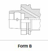
Available sizes: 40, 50, 63, 80, 100, 125, 160
HSK-B is a much less common form designed for higher rigidity. The taper will have the holes that often appear in HSK-A, but will not have drive key slots. In addition, HSK-B features a reduced taper size, which allows for greater stability due to the increased surface contact area of the flange.
HSK-C
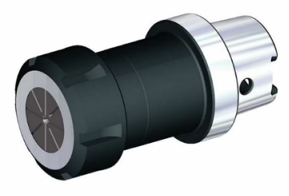
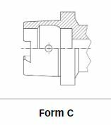
Available sizes: 25, 32, 40, 50, 63, 80, 100, 125, 160
HSK-C is designed for transfer lines and special machines, and has one notable difference from HSK-A: The flange does not feature the groove present in forms A and B, and is often narrower than the flange on those forms as well. Sizing is the same as HSK-A.
HSK-D
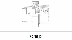
Available sizes: 40, 50, 63, 80, 100, 125, 160
The least common form, HSK-D, can be thought of as a combination of forms B and C. Like HSK-B, it features a reduced taper that has holes but no drive key slots. Like HSK-C, the flange lacks the groove found in forms A and B.
HSK-E
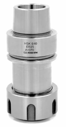
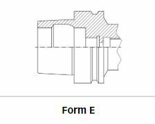
Available sizes: 20, 25, 32, 40, 50, 63
HSK-E is designed for high-speed applications. It has the same grooved flange as HSK-A, but lacks the holes and drive key slots in the taper.
HSK-F
Available sizes: 50, 63, 80
The final HSK form, HSK-F, is probably the second-most common after HSK-A. It is another high-speed form which is nearly identical to HSK-E, having a grooved flange and no holes or drive key slots in the taper, but with the notable difference of having a reduced taper like forms B and D.
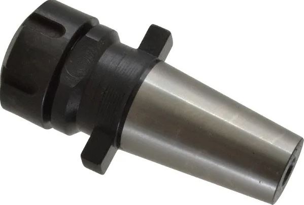
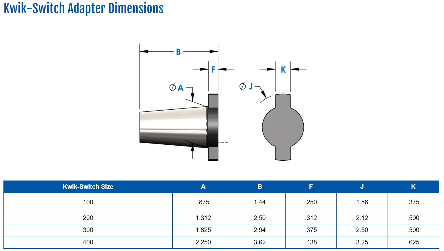
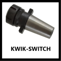
A Kwik-Switch tool holder is far less common, and will have a very different looking flange which is only present on two ends of the tool holder. Unlike other tool holders which are attached directly into a CNC machine, Kwik-Switch holders are inserted into a "Master" holder which adapts to a more common shank style such as CAT, NMTB, or even straight shank.
There are different Kwik-Switch sizes which can be determined by measuring with calipers at the bottom of the taper shank (A on the diagram above).
Quick Change Holder Master Holder Quick Change Holder Inserted Into Master Holder
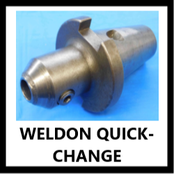
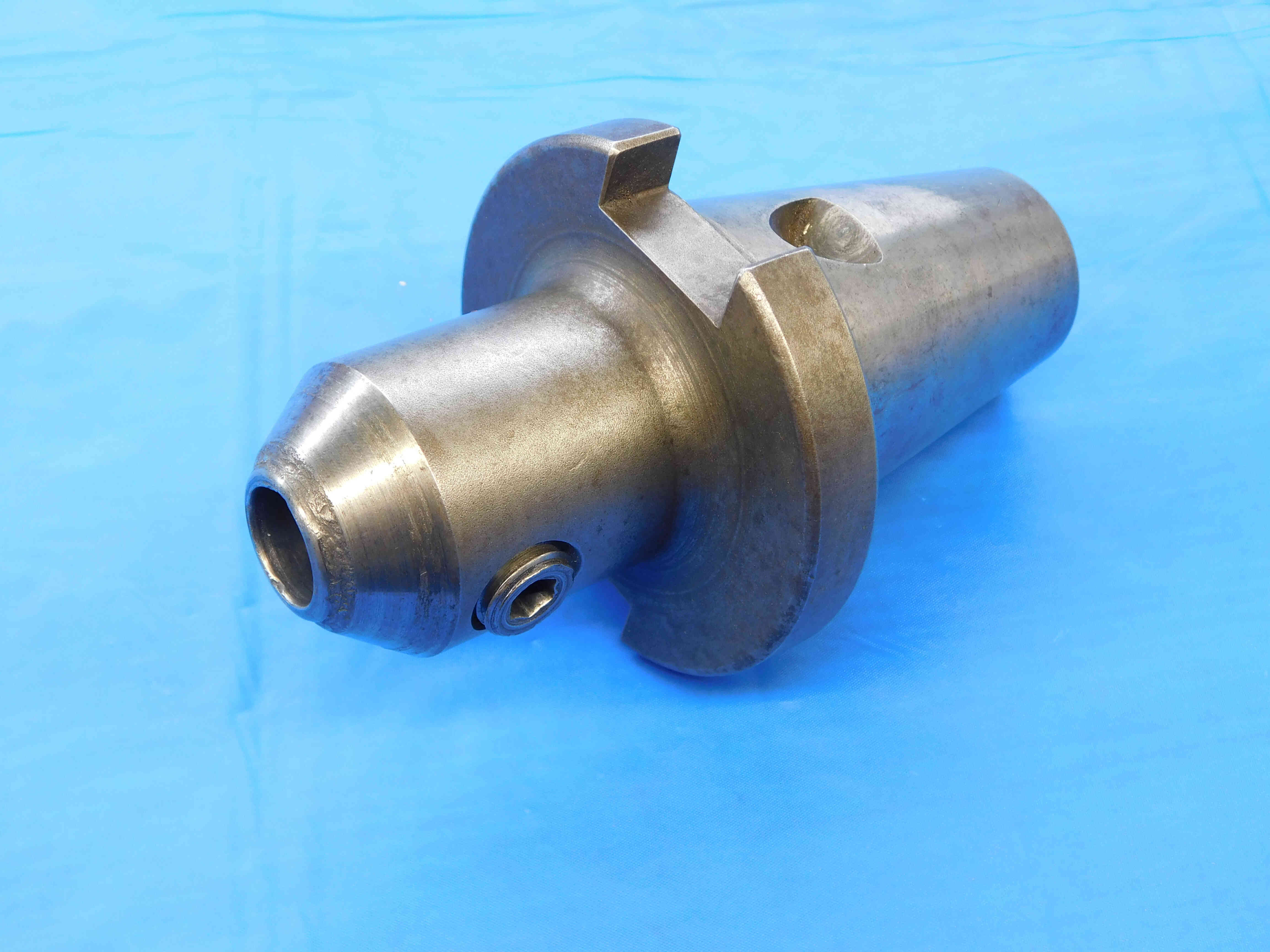
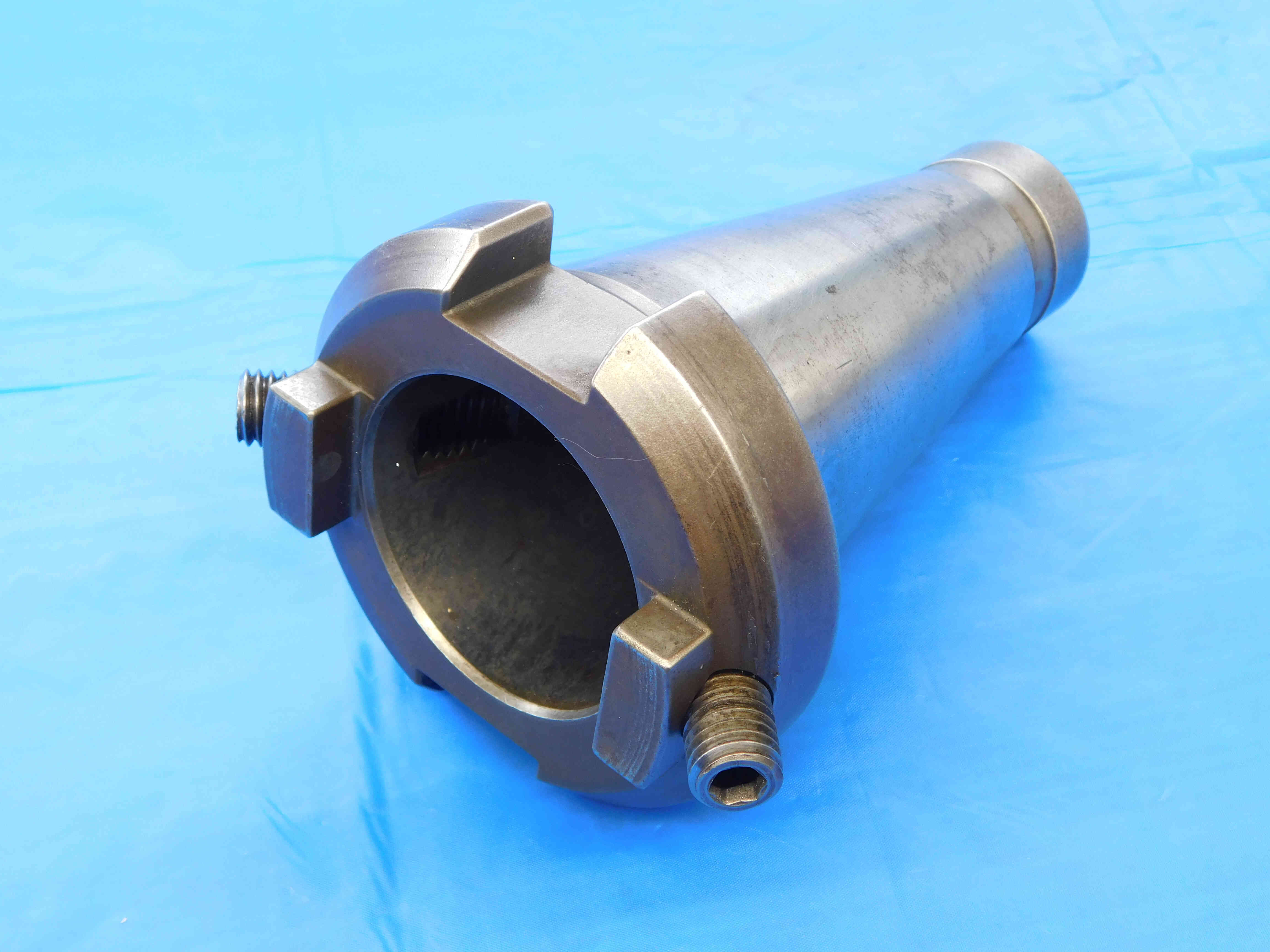
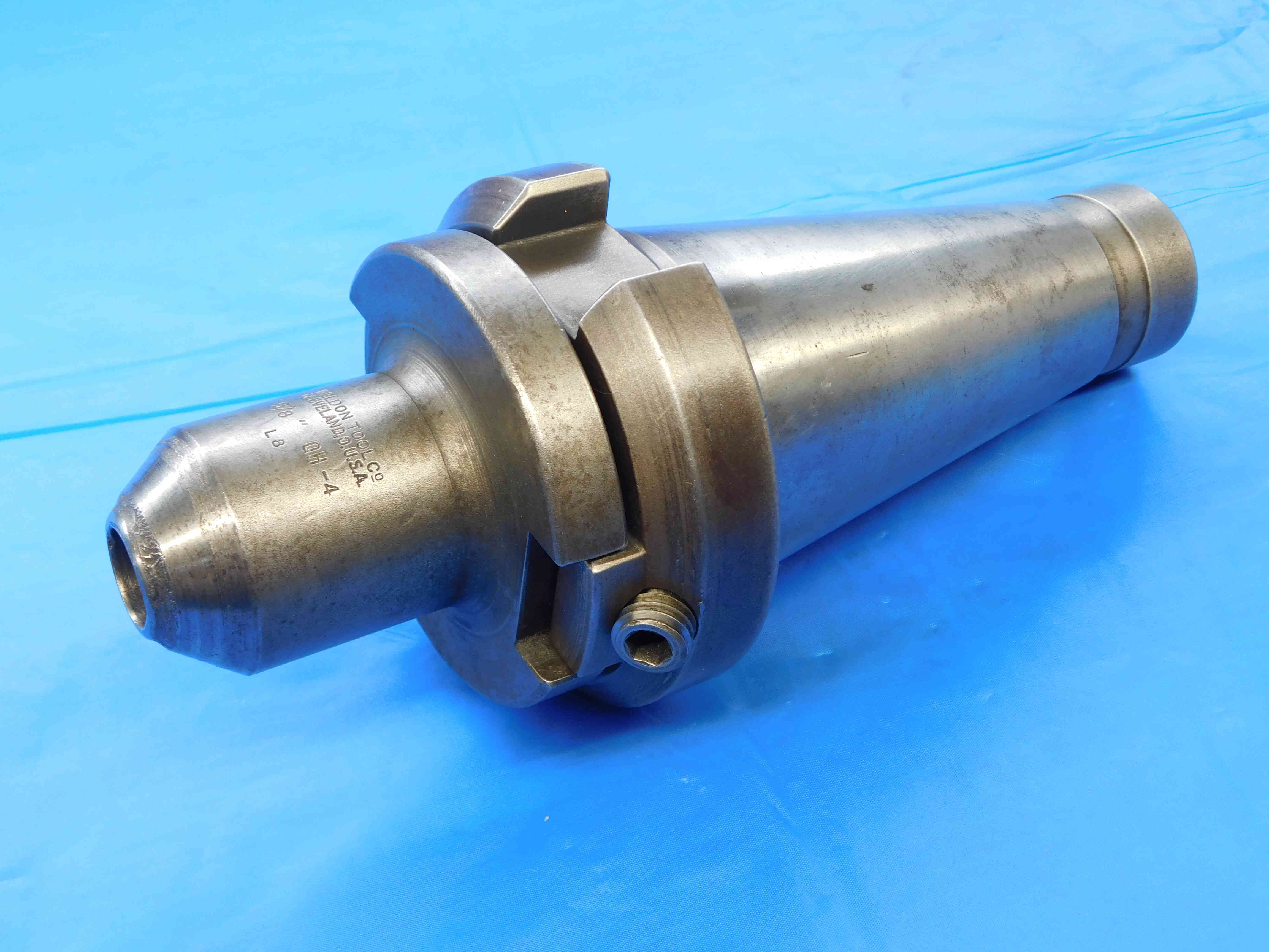
Similar to Kwik-Switch, Weldon-brand quick-change tool holders also use a Master holder to convert their unique taper to a more common style such as CAT or NMTB. They are affixed to the master holder by using set screws which lock into the two distinctive notches on either side of the taper. Unlike Kwik-Switch, however, these quick-change tool holders do not come in multiple sizes.
(Click an icon below to jump to that section)
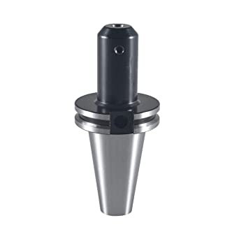
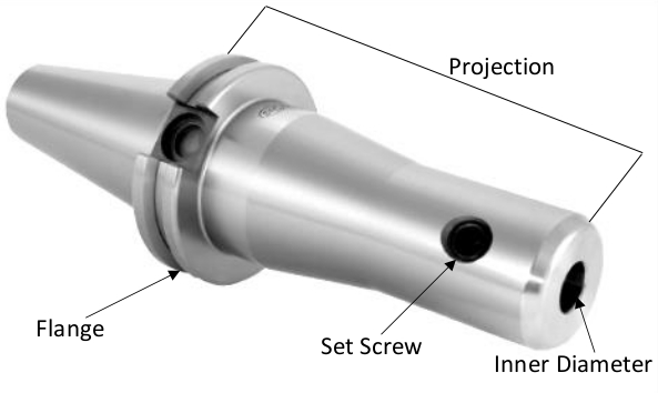
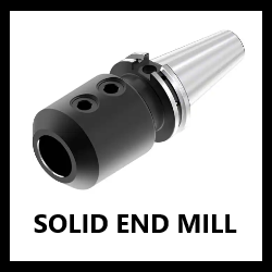
End mill holders have one solid inner diameter (I.D.) that does not taper, and always have 1 or more set screws that hold the tooling rigid. These are readily available and economical for milling.
Their inner diameter size can be measured with calipers and is often labeled on the flange. This will almost always be a common "on-size" (such as 1/2", 3/8", 1 1/4", etc.), however this is a precise measurement and should not be rounded if it is more than .005" off from a fractional size. If you are getting an unusual "off-size" measurement, try converting to millimeters as it may be a metric size.
Projection is measured from the top of the flange to the very end of the holder and can be measured with calipers or even a tape measure as this measurement does not need to be so precise.
Note: When entering a whole-number inch size, always include the " sign. The " sign should not be included for any size including a fraction or decimal. So, for example: If a tool holder's I.D. is exactly one inch, it should be entered as 1" and not just 1. If the I.D. is one and a half inches, it should be entered as 1 1/2 or 1.5 and not 1 1/2" or 1.5".
Metric size measurements should be entered with a lowercase "mm" (ex.: 16mm, 40mm).
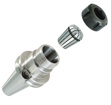
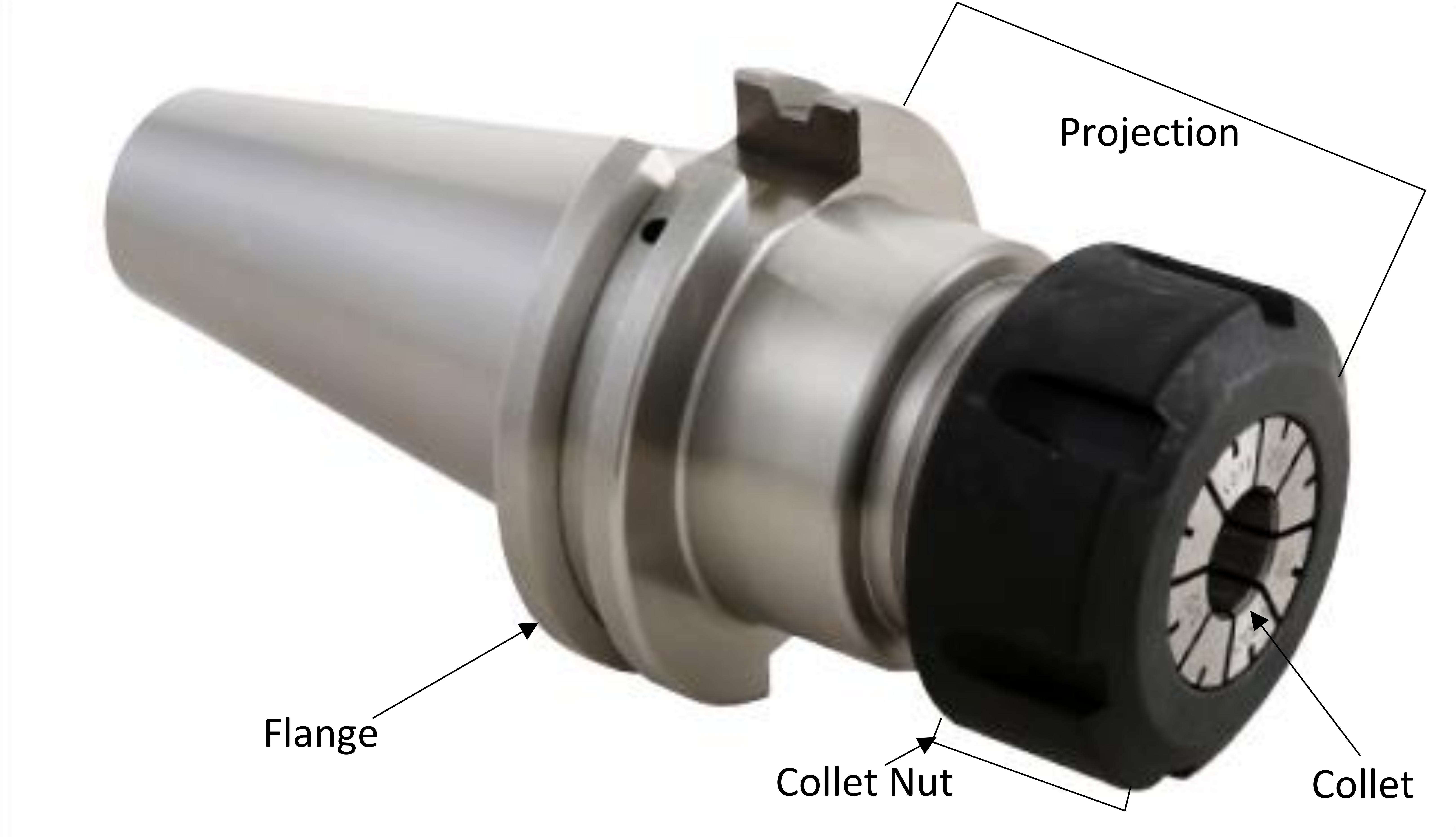
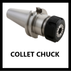
Collet chuck holders hold various types of collets, the most common being TG, ER, & DA. They come with a collet nut that can either be hex or slotted which is threaded on & off to secure the collets that hold the tooling.
For information about collets and how to identify different types, refer to the Collets information page.
Projection is measured from the top of the flange to the end of the collet nut when it is loosely tightened. This can be measured with calipers or a tape measure.
Note: When entering a whole-number inch size, always include the " sign. The " sign should not be included for any size including a fraction or decimal. So, for example: If a tool holder's projection is exactly three inches, it should be entered as 3" and not just 3. If the projection is three and a half inches, it should be entered as 3 1/2 or 3.5 and not 3 1/2" or 3.5".
Metric size measurements should be entered with a lowercase "mm" (ex.: 16mm, 40mm).
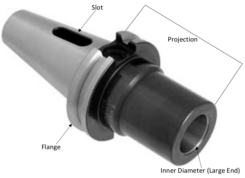
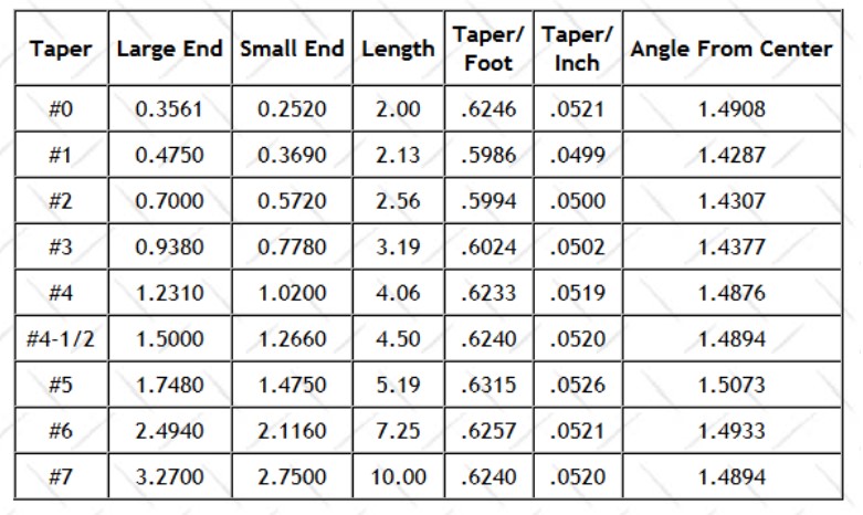
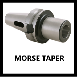
As the name implies, the inner diameter in these tool holders is tapered. There are no set screws and the tooling is fit by a male / female component. There will always be a slot in the taper shank seen in the picture above.
To find what size MT (Morse Taper) you have, measure the largest point of the inner diameter with calipers and compare to the "Large End" on the chart seen above. Projection is measured from the top of the flange to the end of the holder and can be measured with calipers or a tape measure.
Note: When entering a whole-number inch size, always include the " sign. The " sign should not be included for any size including a fraction or decimal. So, for example: If a tool holder's projection is exactly three inches, it should be entered as 3" and not just 3. If the projection is three and a half inches, it should be entered as 3 1/2 or 3.5 and not 3 1/2" or 3.5".
Metric size measurements should be entered with a lowercase "mm" (ex.: 16mm, 40mm).
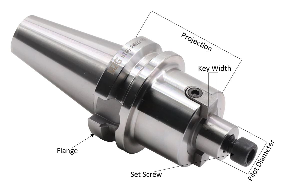
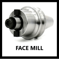
Face / shell mill holders will have a male pilot and key that a mill will fit into. A set screw should be present in the pilot and will hold the mill in place.
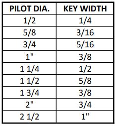
Both pilot diameter and key width can be measured with calipers and correspond to the face / shell mill size. Pilots and keys sometimes measure undersize due to wear, so it is okay to round up if you are close to a common size (pilots and keys should always be common sizes). There are several common pilot / key size combinations that most face mill holders will adhere to, outlined in the chart below:
Projection is measured from the top of the flange to the large face where the face mill will sit (note that the projection does not extend all the way to the end of the pilot) and can be measured using calipers or a tape measure.
Note: When entering a whole-number inch size, always include the " sign. The " sign should not be included for any size including a fraction or decimal. So, for example: If a face mill holder's pilot O.D. is exactly one inch, it should be entered as 1" and not just 1. If the O.D. is one and a half inches, it should be entered as 1 1/2 or 1.5 and not 1 1/2" or 1.5".
Metric size measurements should be entered with a lowercase "mm" (ex.: 16mm, 40mm).
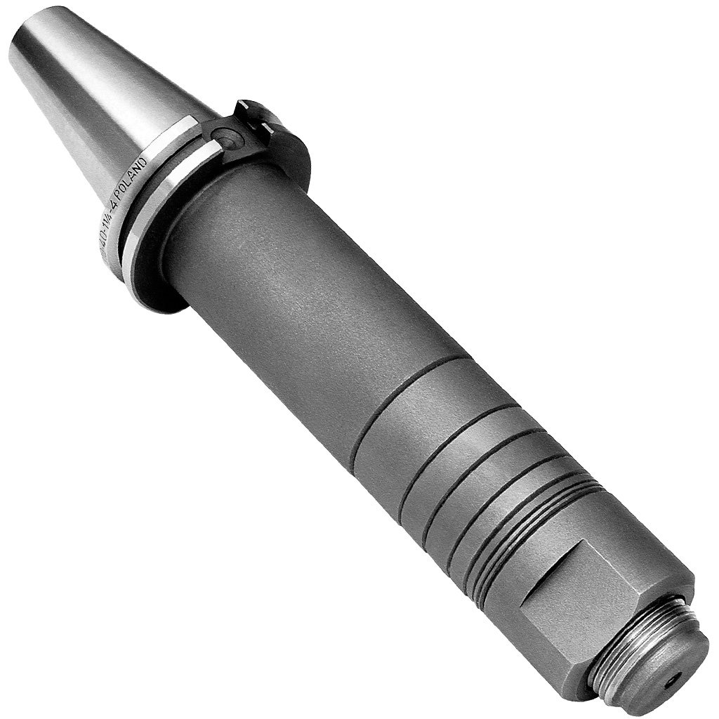
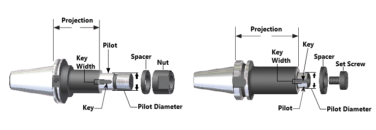
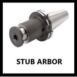
Similar to face / shell mill holders, stub arbors and flush arbors have a pilot and key which are used to hold side milling cutters. There will often be one or more spacers present as well, which are used for placing the cutter at the correct position along the arbor.
The end of the arbor will have either external threading with a nut, which makes it a stub arbor (shown above on the left), or internal threading with a set screw, which makes it a flush arbor (shown above on the right).
The pilot diameter and key width can be measured using calipers and will typically be common sizes. Projection is measured from the top of the flange to the point where the pilot begins, using calipers or a tape measure. Many stub arbors will have spacers which are used to extend the projection, but these should not be included in this listed measurement.
Note: When entering a whole-number inch size, always include the " sign. The " sign should not be included for any size including a fraction or decimal. So, for example: If a tool holder's projection is exactly three inches, it should be entered as 3" and not just 3. If the projection is three and a half inches, it should be entered as 3 1/2 or 3.5 and not 3 1/2" or 3.5".
Metric size measurements should be entered with a lowercase "mm" (ex.: 16mm, 40mm).
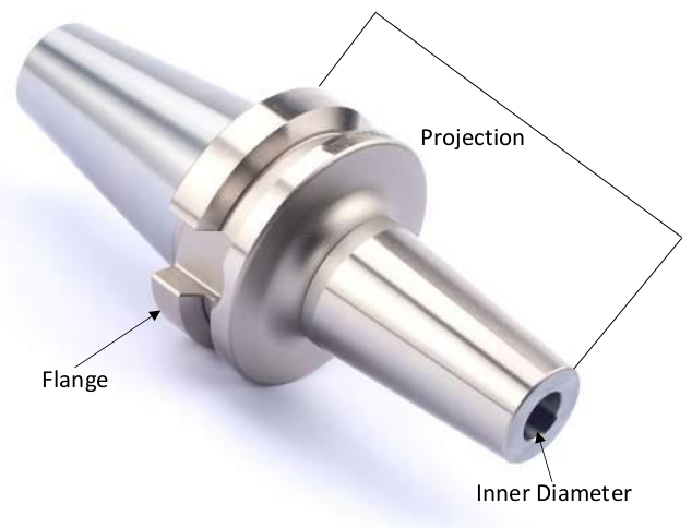
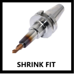
Shrink Fit holders will have a solid inner diameter (I.D.) similar to other milling holders, but do not have set screws. They are slimmer and have excellent gripping force. They are heated when changing tools, expanding the diameter and cooled to provide an interference fit.
The inner diameter size is measured with calipers similar to solid end mill holders. Like with solid end mill holders, this will typically be a common "on-size", but should not be rounded if it is more than .005" off from a fractional size. Shrink fit holders are also commonly metric sizes, so if you are getting an unusual "off-size" try converting to millimeters.
Projection is measured from the top of the flange to the very end of the holder using calipers or a tape measure.
Note: When entering a whole-number inch size, always include the " sign. The " sign should not be included for any size including a fraction or decimal. So, for example: If a tool holder's I.D. is exactly one inch, it should be entered as 1" and not just 1. If the I.D. is one and a half inches, it should be entered as 1 1/2 or 1.5 and not 1 1/2" or 1.5".
Metric size measurements should be entered with a lowercase "mm" (ex.: 16mm, 40mm).
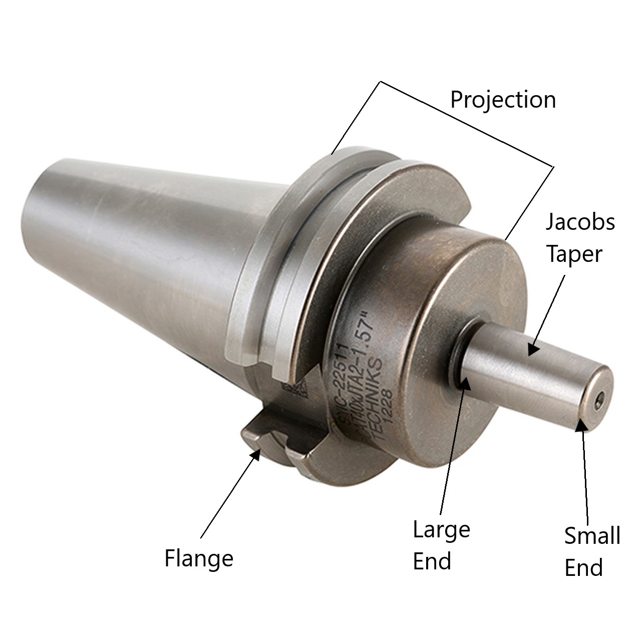
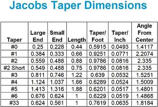
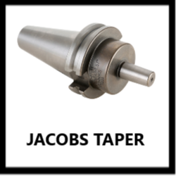
Jacobs Taper tool holders work similarly to Morse Taper tool holders, except that this time the tool holder has the male taper, which fits into the female taper of a drill chuck. The taper size can be measured by the large or small end according to the chart above.
Projection is measured from the top of the flange to the base of the taper (note that the projection does not extend all the way to the end of the taper) and can be measured with calipers or a tape measure.
Note: When entering a whole-number inch size, always include the " sign. The " sign should not be included for any size including a fraction or decimal. So, for example: If a tool holder's projection is exactly three inches, it should be entered as 3" and not just 3. If the projection is three and a half inches, it should be entered as 3 1/2 or 3.5 and not 3 1/2" or 3.5".
Metric size measurements should be entered with a lowercase "mm" (ex.: 16mm, 40mm).
For more information about drill chucks, which you may find attached to a Jacobs Taper tool holder, refer to the Drill Chucks information page.
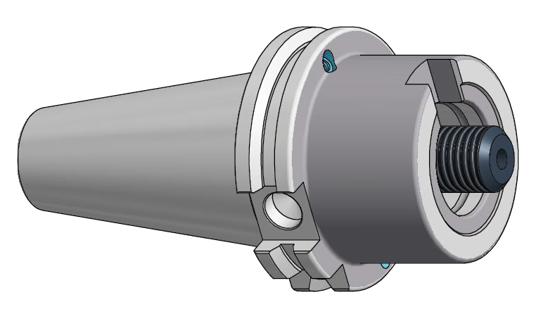
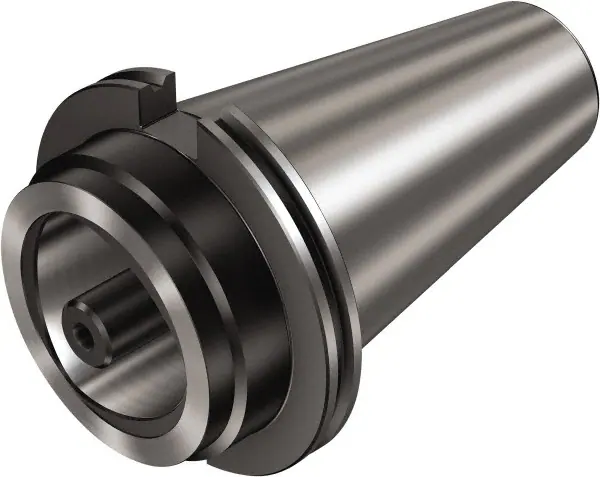
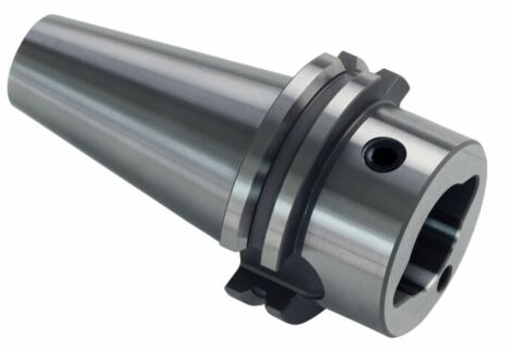
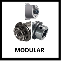
Modular tool holders use special clamping systems to connect to tools that are specifically designed to be used with that corresponding modular system.
Modular tool holders will have both a type and size such as ABS 50 or CAPTO C8. For an in-depth explanation of common types and how to determine their sizes, refer to the Modular Connection Types information page.
For all modular types, projection is measured from the top of the flange to the very end of the tool holder's working end and can be measured with calipers or a tape measure.
Note: When entering a whole-number inch size, always include the " sign. The " sign should not be included for any size including a fraction or decimal. So, for example: If a tool holder's projection is exactly three inches, it should be entered as 3" and not just 3. If the projection is three and a half inches, it should be entered as 3 1/2 or 3.5 and not 3 1/2" or 3.5".
Metric size measurements should be entered with a lowercase "mm" (ex.: 16mm, 40mm).
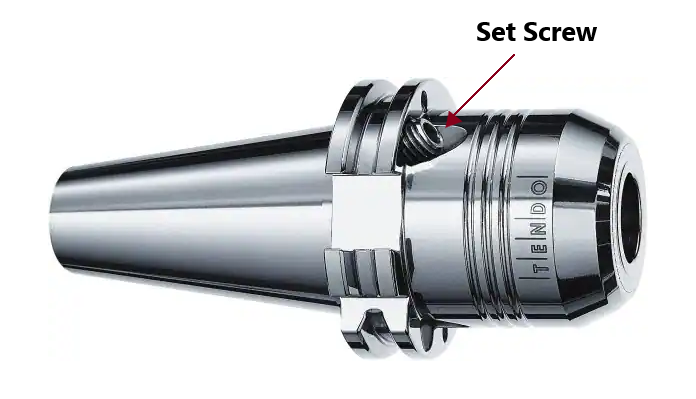
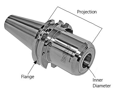
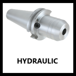
Hydraulic chucks will have set screws much closer to the flange and will have a solid inner diameter (I.D.) similar to end mill holders. They use oil to generate pressure and deform the holder’s ID around the tool shank and provide excellent gripping force.
The inner diameter size is measured with calipers and will usually be either a common fractional or metric size. Like other tool holding types that have an I.D., this should not be rounded if it is more than .005" off from an "on-size".
Projection is measured from the top of the flange to the very end of the holder using calipers or a tape measure.
Note: When entering a whole-number inch size, always include the " sign. The " sign should not be included for any size including a fraction or decimal. So, for example: If a tool holder's I.D. is exactly one inch, it should be entered as 1" and not just 1. If the projection is one and a half inches, it should be entered as 1 1/2 or 1.5 and not 1 1/2" or 1.5".
Metric size measurements should be entered with a lowercase "mm" (ex.: 16mm, 40mm).
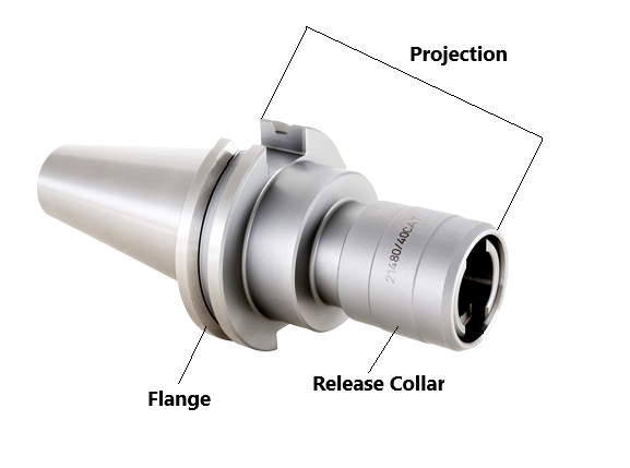
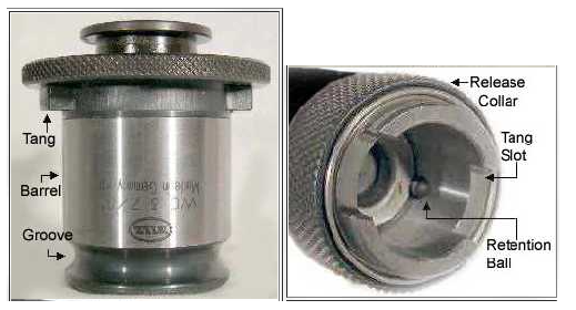
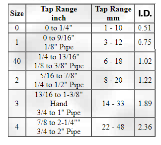
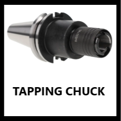
Tapping chucks are essentially a variation of collet chucks. They use quick-change tap collets (pictured above) which are held in place by a "Tang Drive" system and can be quickly removed by pressing the release collar in toward the tool holder. Like regular collets, these come in different sizes which should be included in the listing. If the collet size is not labeled, it can be determined by measuring the inner diameter of the chuck and comparing to the chart above.
There are two types of tapping chucks: Rigid Tapping Chucks and Tension & Compression Tapping Chucks.
A rigid tapping chuck, like the name implies, has no moving parts besides the release collar and holds a tap rigidly with no extra movement. Rigid tapping is often faster and produces a more accurate thread, but requires precise synchronization between the motion of the machine spindle and the axis moving down the hole - and improper synchronization can lead to torn threads and broken taps.
A tension & compression tapping chuck, meanwhile, has a free-floating head that uses springs to allow a small amount of movement in the tap, compensating for errors as the machine pushes and pulls the tap through the material. Tension & compression tapping chucks tend to be more expensive, and are less useful for working with softer materials which can deform around the tap.
How to tell the difference: On both types of chucks the collar will be able to be pulled out away from the flange (which is how the collet is released), but a tension & compression chuck will also be able to be pushed in toward the flange, while a rigid chuck will not. This is where the "compression" part of tension & compression comes from, and is the easiest way to distinguish the two types since in most cases there will otherwise be no visual differences.
Two other types of tapping chucks you may encounter are the Kennametal/Erickson DA Tapping Series described here, and the Numertap system developed by Parlec:
Numertap
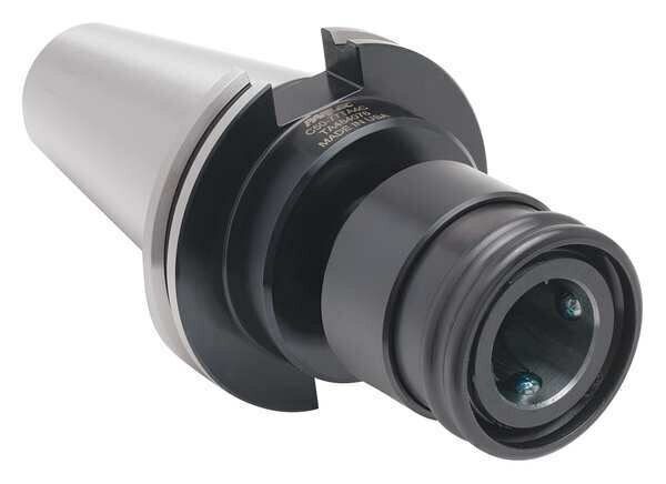
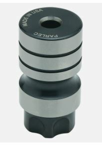
Numertap chucks use a unique collet, pictured above, which is longer than the Bilz style, does not have tangs, and is held in place by ball bearings on the inside of the receiving chuck. These chucks can be rigid or tension & compression just like Bilz-style chucks.
Numertap collets come in a few different sizes, which can be determined by measuring the O.D. of the collet or the I.D. of the chuck, according to the chart below:

*Sizes 700 and 770 are interchangeable
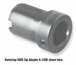
**Numertap 6000 uses a different unique collet which resembles a lathe bushing, shown below:
Projection on all tapping chucks is measured from the top of the flange to the end of the tapping chuck using calipers or a tape measure.
Note: When entering a whole-number inch size, always include the " sign. The " sign should not be included for any size including a fraction or decimal. So, for example: If a tool holder's projection is exactly three inches, it should be entered as 3" and not just 3. If the projection is three and a half inches, it should be entered as 3 1/2 or 3.5 and not 3 1/2" or 3.5".
Metric size measurements should be entered with a lowercase "mm" (ex.: 16mm, 40mm).
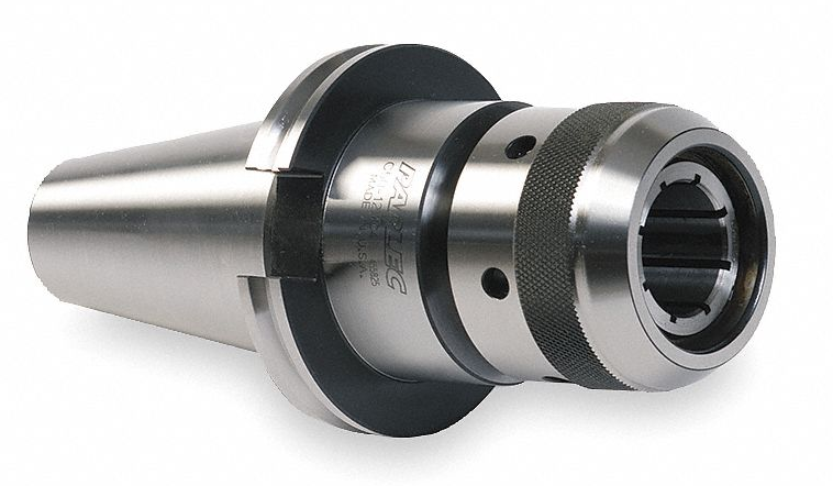
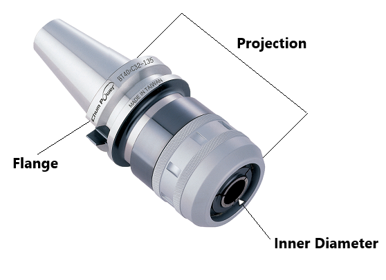
Milling chucks use a twist-lock gripping system like that used by drill chucks. They have a solid inner diameter (I.D.) similar to other tool holding types, but can also use a straight collet to allow the holding of smaller tools. The most common of these collets is the KM1 series made by Lyndex-Nikken, and so "KM1" should be included as a "filler" term in the title whenever possible.
The inner diameter size can be measured with calipers. It will typically be a common fractional or metric size, but should not be rounded if it more than .005" off from an "on-size" measurement.
Projection is measured from the top of the flange to the very end of the holder and can be measured using calipers or a tape measure.
Note: When entering a whole-number inch size, always include the " sign. The " sign should not be included for any size including a fraction or decimal. So, for example: If a tool holder's projection is exactly three inches, it should be entered as 3" and not just 3. If the projection is three and a half inches, it should be entered as 3 1/2 or 3.5 and not 3 1/2" or 3.5".
Metric size measurements should be entered with a lowercase "mm" (ex.: 16mm, 40mm).
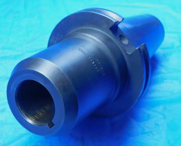
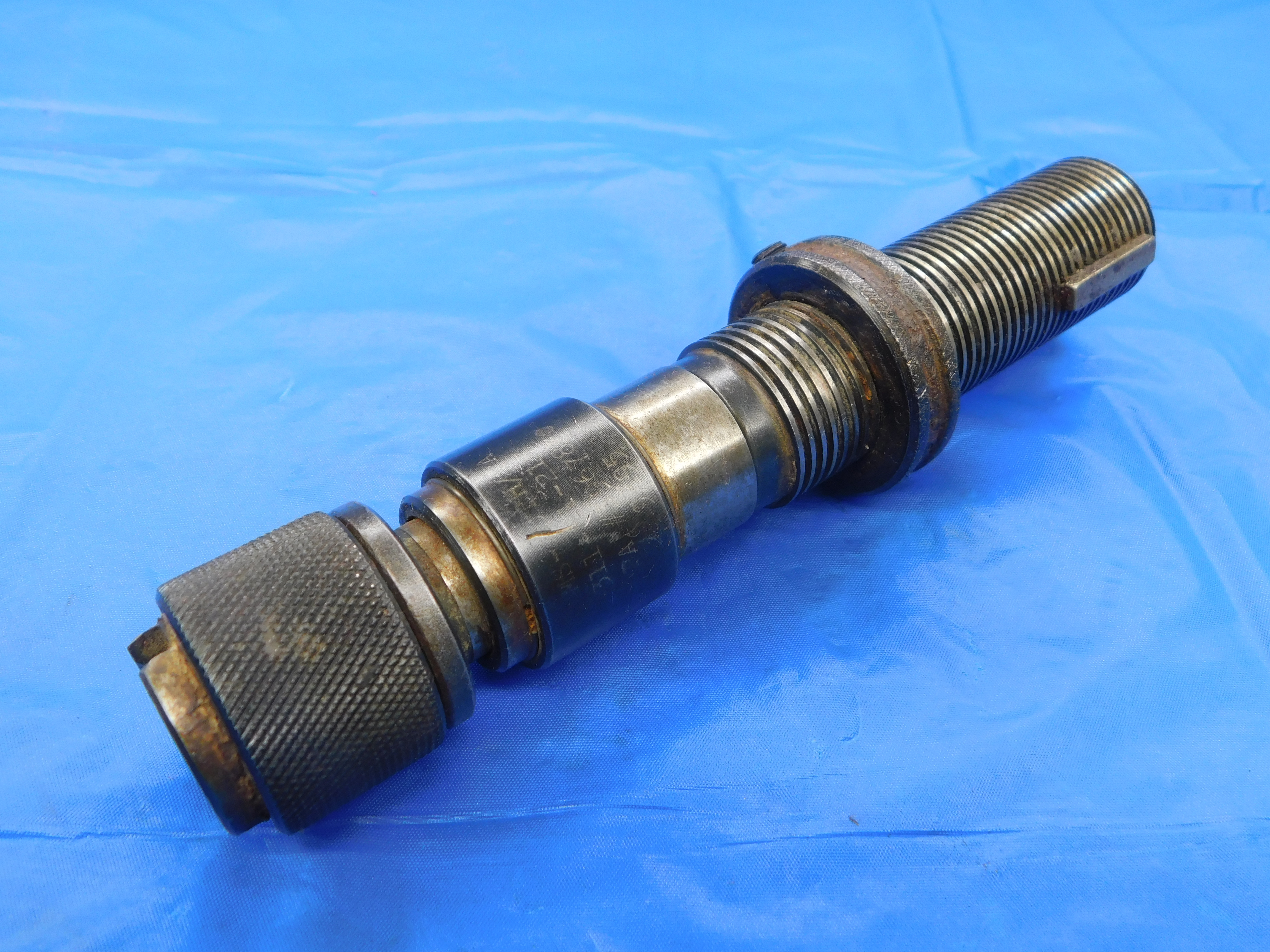
Some tools, like the one shown above on the right, have a type of shank called an Automotive Shank, or Auto Shank for short. This is a straight shank with external threading and a smooth, raised drive key on one side. There is typically a collar which can be threaded up and down the shank to adjust how far the tool projects from its holder.
Auto Shank tool holders are visually very similar to Solid End Mill tool holders, with a straight Inner Diameter and one or more set screws. The main difference is the Keyway which the drive key on the auto shank slots into in order to keep the tool from spinning freely within the holder. The Keyway Width should be included in the listing along with the I.D.
Projection is measured from the top of the flange to the very end of the holder and can be measured using calipers or a tape measure.
Note: When entering a whole-number inch size, always include the " sign. The " sign should not be included for any size including a fraction or decimal. So, for example: If a tool holder's projection is exactly three inches, it should be entered as 3" and not just 3. If the projection is three and a half inches, it should be entered as 3 1/2 or 3.5 and not 3 1/2" or 3.5".
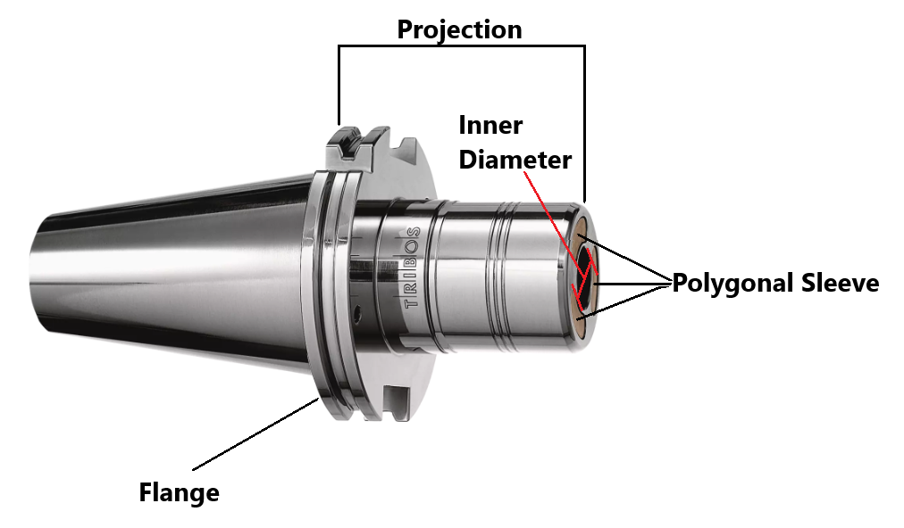
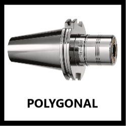
Schunk's "TRIBOS" series of polygonal tool holders uses a special elastic sleeve that is fitted around a tool using a specialized clamping machine. This form-fitted holding style drastically reduces vibration and runout.
The inner diameter size can be measured with calipers. It will typically be a common fractional or metric size, but should not be rounded if it more than .005" off from an "on-size" measurement.
Projection is measured from the top of the flange to the very end of the holder and can be measured using calipers or a tape measure.
Note: When entering a whole-number inch size, always include the " sign. The " sign should not be included for any size including a fraction or decimal. So, for example: If a tool holder's I.D. is exactly one inchs, it should be entered as 1" and not just 1. If the I.D. is one and a half inches, it should be entered as 1 1/2 or 1.5 and not 1 1/2" or 1.5".
Metric size measurements should be entered with a lowercase "mm" (ex.: 16mm, 40mm).
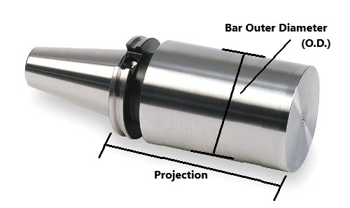
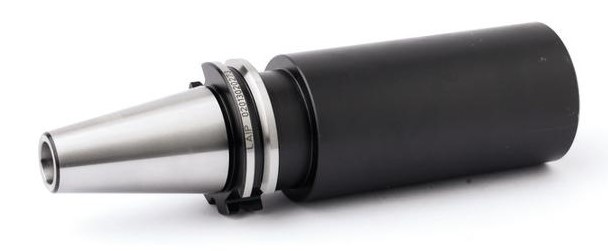
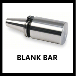
Tool holder blanks are machinable bars which can be converted into custom tools or holders by a machine shop. The bar diameter, which can be measured with calipers, should always be included in the listing. Projection is measured from the top of the flange to the end of the bar.
Note: When entering a whole-number inch size, always include the " sign. The " sign should not be included for any size including a fraction or decimal. So, for example: If a tool holder's projection is exactly three inches, it should be entered as 3" and not just 3. If the projection is three and a half inches, it should be entered as 3 1/2 or 3.5 and not 3 1/2" or 3.5".
Metric size measurements should be entered with a lowercase "mm" (ex.: 16mm, 40mm).
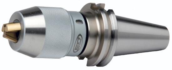
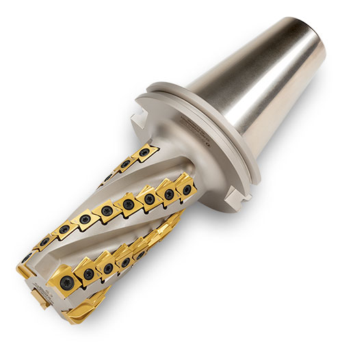
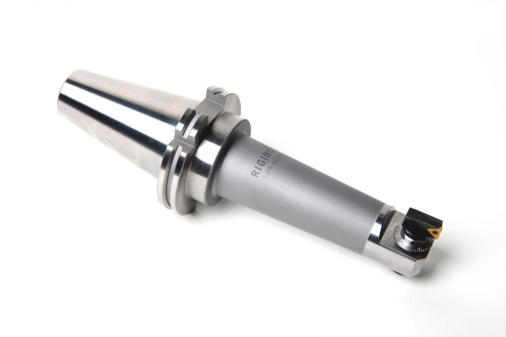
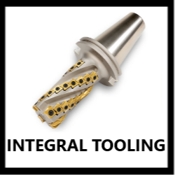
Some tool holders, rather than being able to hold a variety of tools, will have a single integral tool that is actually part of the tool holder itself. This can be anything from drill chucks, to boring heads, to indexable drills or end mills and more. In general, it is better to list these tools using the corresponding template category (drill chuck, boring head, etc.) rather than the tool holder category. This will make it easier to include all of the relevant information about the tool in the listing. In this case you would enter the Taper Shank Style and Size (CAT50, NMTB40, etc.) as the shank size for the tool (NOTE: For some tool types, this might cause issues with the title formatting which will require manual editing. Contact your trainer if you need help determining the proper title for a listing).
For a variety of reasons, tooling is sometimes unable to be removed from a tool holder. If a tool holder is being listed with a tool in it, use this section to describe the included tool as specifically as you can. Additional information can be included in the "Additional Specifications" section if there is not enough room in the title.
If you have a large amount of information to include about the held tooling, it is often better to list the item using the corresponding template category (face mill, drill chuck, etc.) instead of the tool holder category. This will make it easier to include all of the relevant information about the tool. In this case, once all information has been entered, you should manually edit the title to include, for example, "W/ CAT50 TOOL HOLDER". Specific information about the tool holder can be included in the "Additional Specifications."
Please note that not all tooling should be specifically advertised in this way. In particular, non-indexable cutting tools such as drills and end mills should be ignored in the listing - it is very possible for these types of tools to be damaged during storage or shipping, and so we do not want customers to think they are getting a usable, working tool when we cannot necessarily guarantee it will still be in that condition when they receive it. For this reason, these types of tools should always have the following note included in the "Special Condition" section: "YOU ARE PURCHASING THE PICTURED TOOL HOLDER. THE HELD TOOLING IS INCLUDED BECAUSE WE WERE NOT ABLE TO REMOVE IT WITH THE TOOLS ON HAND, AND IS NOT GUARANTEED TO BE IN WORKING CONDITION."
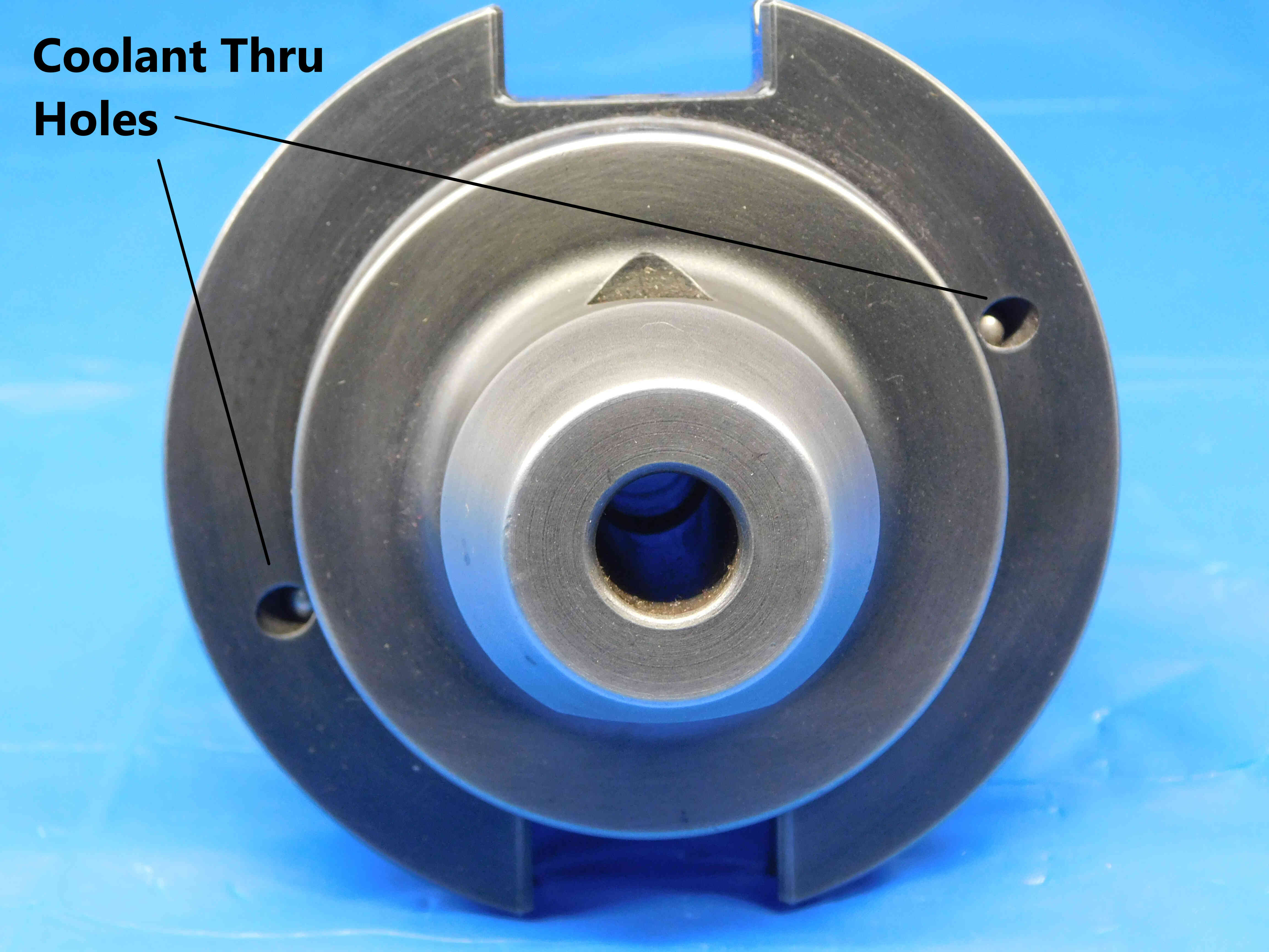
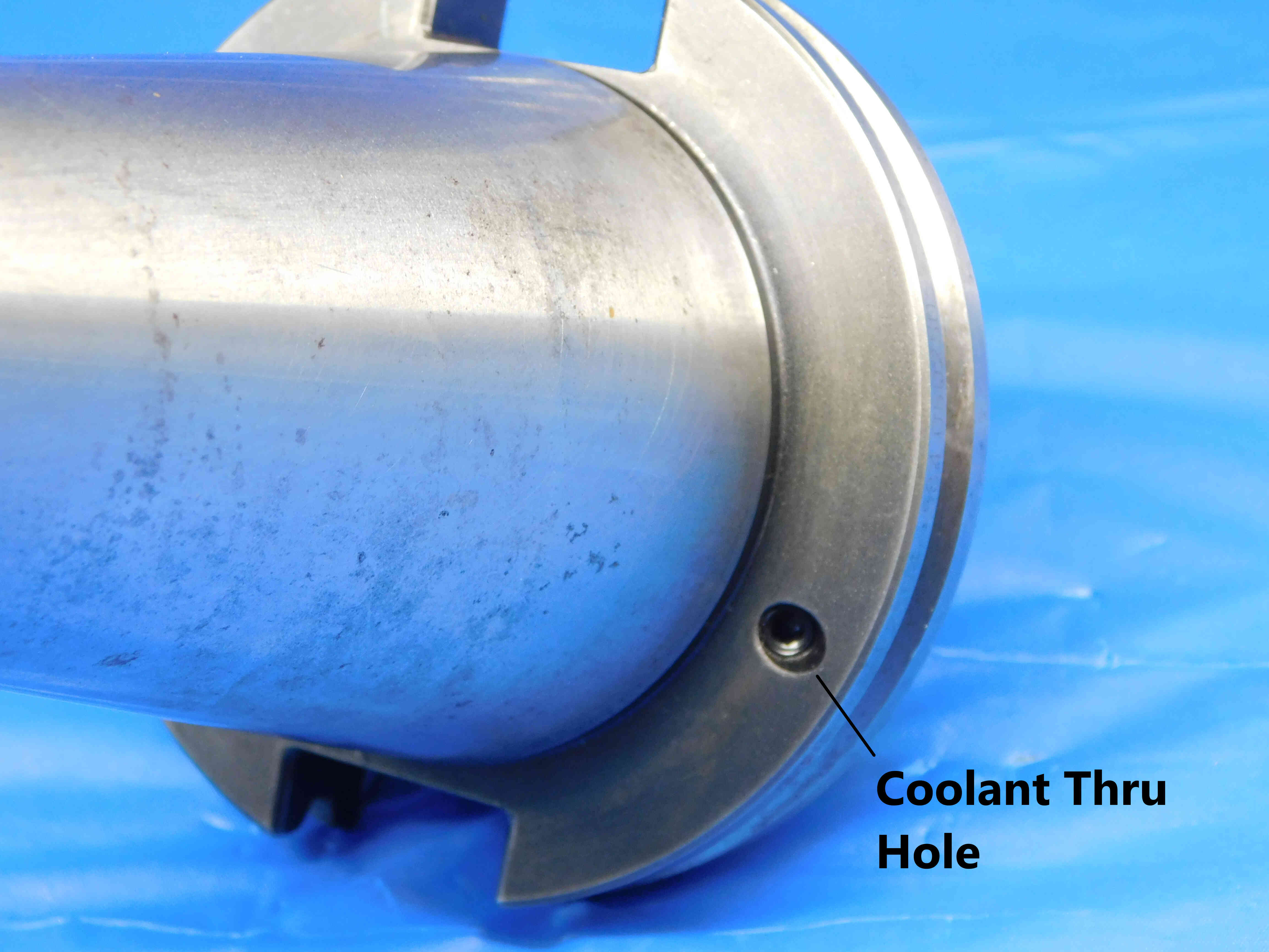
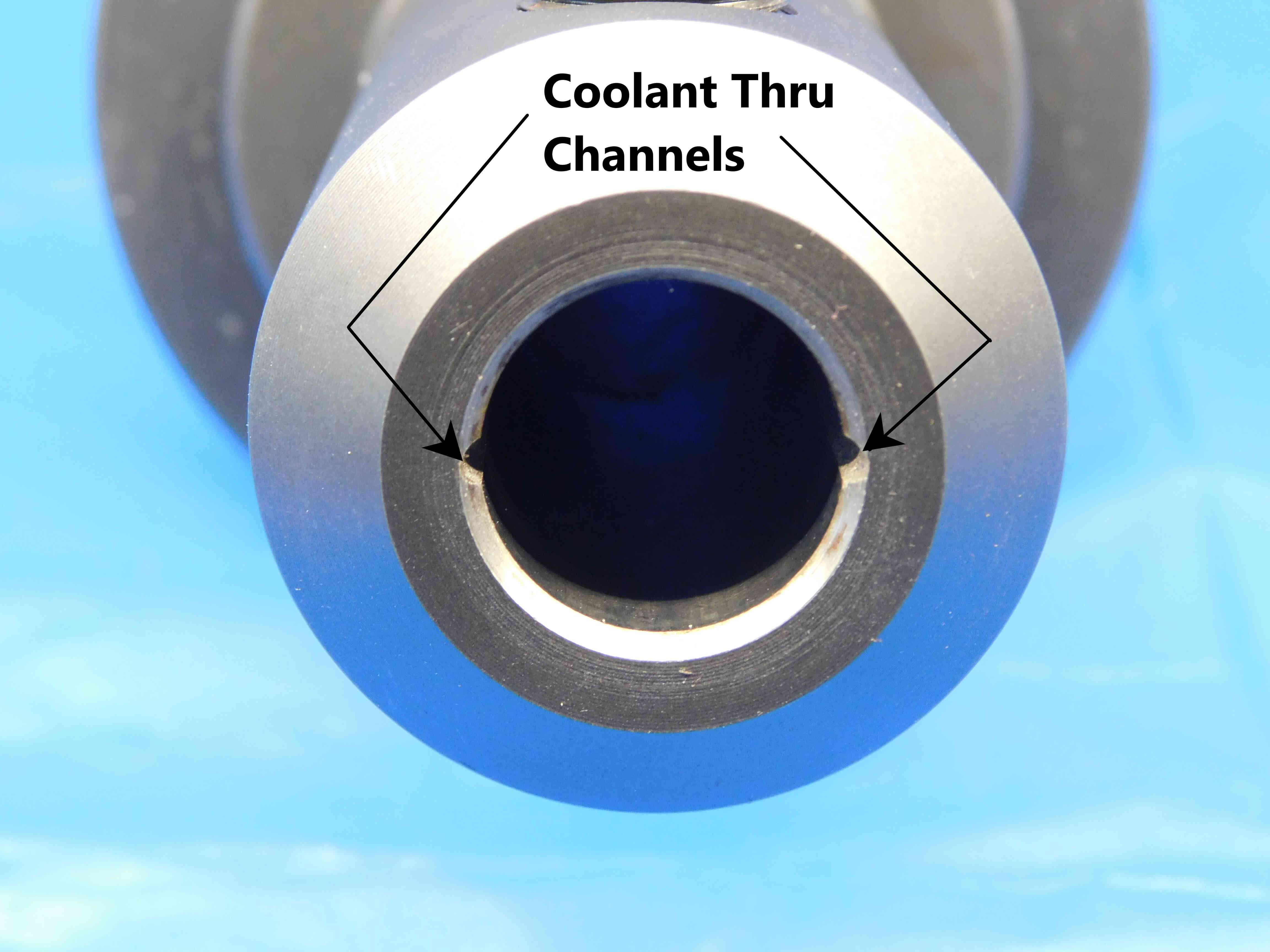
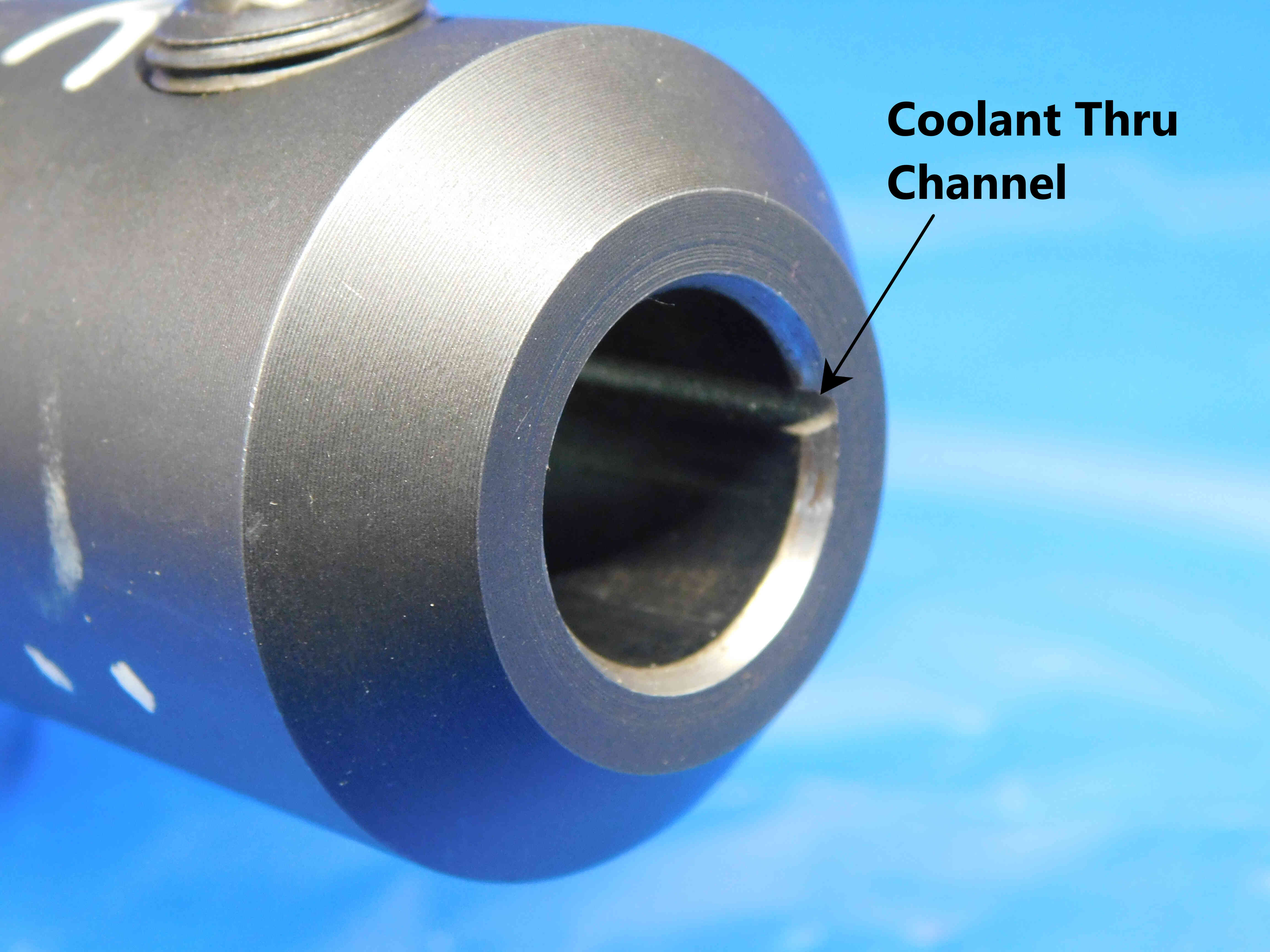
Some tool holders are designed to be coolant-through in order to protect the tool and workpiece from overheating. Coolant ports are most commonly located in the flange, but can also appear in other places such as the end of the tool holder's working end, where they might appear as channels that run down the length of the inner diameter. Coolant-thru tool holders are more valuable than non-coolant thru, so it is very important to check all tool holders for coolant ports.
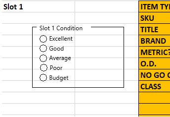
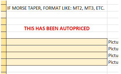
Some tool holders have their prices calculated automatically by the template. When this happens, red text saying "THIS HAS BEEN AUTOPRICED" will appear on the right side of the page.
Whenever an item is auto-priced, you must always select one of the five conditions from the box on the left side of the page (shown above). This will affect the pricing of the item, and there can often be a big difference in price range from Excellent to Budget.
This is a mostly subjective decision which will not necessarily have one correct answer. The most important thing to consider is the condition of the working end, although different types of tool holders will have different aspects to look out for. If you are unsure which condition option to use for an auto-priced tool holder, contact your trainer for guidance.
The "Filler" section is used to add other relevant information to the title which is not covered by the other sections. Fillers can be a good way to increase a listing's visibility - we always want to include as much information as possible that we think a customer might be searching for in order to make sure that our listing is coming up in their search results.
There is not necessarily one right answer when it comes to fillers, and often it will be up to you to decide what should and should not be added as filler. Tool holders generally do not require much filler, but some possible fillers include:
-Secondary Labeling
-Important measurements or other information related to a held or integral tool
-"Quick Change" for tapping chucks
-"USA" or "USA Made" for US Manufacturers (this may require quickly researching the brand if you are not sure, since this is not always specifically labeled)
Note: Keep in mind that titles have a maximum limit of 80 characters.
Additional Specifications & Special Condition
The Additional Specifications section should be used for any secondary labeling or additional measurements that do not fit in the other sections of the listing. There is no character limit here so any relevant information that is not already covered should be included (within reason - we don't want to overload the listing with unnecessary information, so ask your trainer if you are not sure whether or not to include something in this section).
The Special Condition section should be used for any special notes about the item's condition such as damage or modification. Try to be specific when describing the condition, and reference pictures that point out the damage / modification if applicable. For example, "This is missing one set screw" or "One of the keys is cracked - see picture #5". General wear and tear does not need to be mentioned, but anything that will affect the tool's usage should be included here.
Once all information is entered, click here for the next steps.

